
Toyota Corolla (E120) 2002–2008 Repair Manual / Supplemental restraint system / Spiral cable sub–assy
Toyota Corolla (E120): Spiral cable sub–assy
Components
Replacement
Hint
: components:
1. Precaution
2. Disconnect battery negative terminal
3. Place front wheels facing straight ahead
- check that the front wheels are facing straight ahead.
4. Remove horn button assy
5. Remove steering wheel assy
sst 09950–50013 (09951–05010, 09952–05010, 09953–05020, 09954–05021)
6. Remove steering column cover
7. Remove spiral cable sub–assy
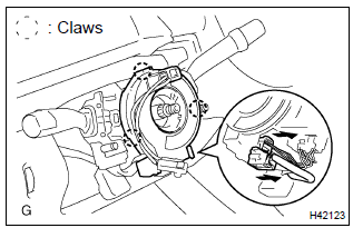
- Disconnect the airbag connector and the connector from the spiral cable sub–assy.
- release the 3 claws and remove the spiral cable sub– assy.
8. Inspect spiral cable sub–assy
- if the following condition is identified, replace the spiral cable sub–assy with a new one.
Condition
: scratches or cracks on the connector cracks, dents or chipping of the spiral cable sub–assy
9. Place front wheels facing straight ahead
- check that the front wheels are facing straight ahead.
10. Install spiral cable sub–assy
- set the turn signal switch in neutral position.
Notice
: make sure of the neutral position since the pin of the turn signal switch may be snapped.
- engage the 3 claws and install the spiral cable sub–assy.
Notice
: when replacing the spiral cable sub–assy with a new one, remove the lock pin before installing the handle.
- connect the airbag connector and the connector connecting to the spiral cable sub–assy.
- install the steering column cover with the 3 screws.
11. Center spiral cable
- check that the ignition switch is turned to off.
- check that the battery negative terminal is disconnected.
Notice
: do not start the operation for 90 seconds after removing the terminal.
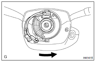
- Turn the cable counterclockwise by hand until it becomes harder to turn.
Hint
: the cable will rotate about 2.5 Turns to either left or right of the center.
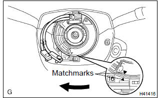
- Then rotate the cable clockwise about 2.5 Turns to align the marks.
12. Install steering wheel assy
torque: 50 nvm (510 kgfvcm, 37 ftvlbf)
13. Install horn button assy
torque: 8.8 Nvm (90 kgfvcm, 78 in.Vlbf)
14. Inspect horn button assy
15. Inspect srs warning light


Other materials:
Basic inspection
When the malfunction is not confirmed in the dtc check, troubleshooting
should be carried out in all the
possible circuits considered as causes of the problem. In many cases, by
carrying out the basic engine check
shown in the following flowchart, the location causing the problem can be found ...
Light control switch circuit
Wiring diagram
Inspection procedure
1 Check headlamp dimmer switch assy (light control switch)
2 Check wire harness (tvip ecu light control switch)
Disconnect the tvip ecu and light control switch connectors.
check the continuity between the terminals of the tvip
e ...
Inspection procedure
1 Check side squib(rh) circuit(airbag sensor assy center – front
seat airbag assy rh)
Disconnect the negative (–) terminal cable from the battery,
and wait at least for 90 seconds.
disconnect the connectors between the airbag sensor
assy center and the front seat airbag assy ...