Toyota Corolla (E120): Overhaul
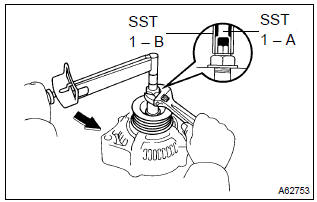
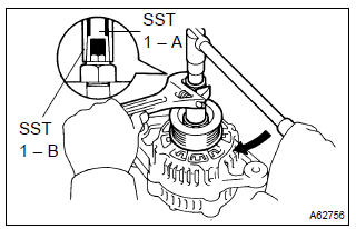
1. Remove generator pulley
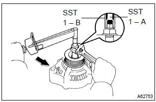
Sst 09820–63010 (09820–06010, 09820–06020)
Hint:

- Hold sst 1 – a with a torque wrench, and tighten sst 1
– b clockwise to the specified torque.
Torque: 39 nvm (398 Kgf·cm, 29 ft·lbf)
Notice
: check that sst is secured to the rotor shaft.
- Mount sst 2 in a vise.
- insert sst 1 – a, b into sst 2, and attach the pulley nut to sst 2.
- To loosen the pulley nut, turn sst 1 – a in the direction
shown in the illustration.
Notice
: to prevent damage to the rotor shaft, do not loosen the pulley nut more than one–half of a turn.
- remove the alternator form sst 2.
- Turn sst 1 – b, and remove sst 1 – a, b.
- remove the pulley nut and pulley.
2. Remove generator brush holder assy
- remove the nut and terminal insulator.
- remove the screw, nut and terminal plate.
- remove the 2 nuts and rear end cover.
- remove the brush cover from the brush holder.
- remove the 2 screw and brush holder.
- remove the plate seal.
3. Remove generator regulator assy
- remove the 3 screws and regulator.
4. Remove generator holder w/rectifier
- remove the 4 screws and holder w/ rectifier.
5. Remove generator rectifier end frame
- Remove the plate seal from the rectifier end frame.
- remove the 4 terminal insulator, 4 nuts and cord clip.
- using sst, remove the rectifier end frame.
Sst 09286–46011
6. Remove generator rotor assy
- remove the washer from the rotor.
- remove the rotor from drive end frame.
7. Inspect generator regulator assy
- Using an ohmmeter, check the continuity between terminals f and b.
Standard
: when the positive and negative poles between terminals f and b are exchanged, there is continuity in one way but no continuity in another way.
- Using an ohmmeter, check the continuity between terminals f and e.
Standard
: when the positive and negative poles between terminals f and e are exchanged, there is continuity in one way but no continuity in another way.
8. Inspect generator regulator assy
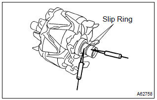
- Using an ohmmeter, check that there is continuity between
the slip rings.
Standard resistance: 2.1 – 2.5 W at 20 c (68 f)
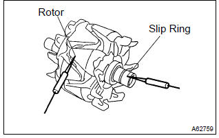
- Using an ohmmeter, check that there is no continuity between the slip ring and rotor.
- Using a vernier calipers, measure the slip ring diameter.
Standard diameter: 14.2 – 14.4 Mm (0.559 – 0.567 In.) Minimum diameter: 12.8 Mm (0.504 In.)
9. Inspect brush
- Using a vernier calipers, measure the exposed brush
length.
Standard exposed length: 9.5 – 11.5 Mm (0.374 – 0.453 In.) Minimum exposed length: 1.5 Mm (0.059 In.)
10. Install generator rotor assy
- Install the rotor to the drive end frame.
- install the washer on the rotor.
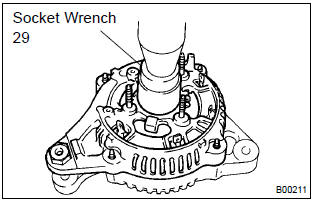
- Using a socket wrench 29 and press, slowly press in the rectifier end frame.
- Install the cord clip and 4 nuts.
Torque:
nut a 4.5 Nvm (46 Kgf·cm, 40 in.Vlbf) nut b 5.4 Nvm (55 Kgf·cm, 48 in.Vlbf)
11. Install generator holder w/rectifier
- install the holder w/ rectifier with 4 screws.
Torque: 2.9 Nvm (30 Kgf·cm, 26 in.Vlbf)
12. Install generator regulator assy
- install the regulator with the 3 screw.
Torque: 2.0 Nvm (20 Kgf·cm, 18 in.Vlbf)
13. Install generator brush holder assy
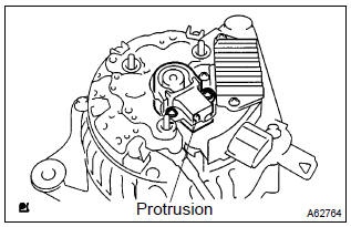
- Place the plate seal on the brush holder.
- install the brush holder with the 2 screws.
Torque: 2.0 Nvm (20 Kgf·cm, 18 in.Vlbf)
Notice
: pay attention to the holder installation direction.
- place the brush cover on the brush holder.
- install the rear end cover with the 2 nuts.
Torque: 4.4 Nvm (45 Kgf·cm, 39 in.Vlbf)
- install the terminal plate with the screw and nut.
Torque:
bolt 3.9 Nvm (40 Kgf·cm, 35 in.Vlbf) nut 4.4 Nvm (45 Kgf·cm, 39 in.Vlbf) - install the terminal insulator withe the nut.
Torque: 4.1 Nvm (42 Kgf·cm, 36 in.Vlbf)
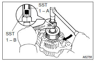
14. Install generator pulley
Sst 09820–63010 (09820–06010, 09820–06020)
Hint:
- Install the pulley to the rotor shaft by tightening the pulley nut by hand.
- hold sst 1 – a with a torque wrench, and tighten sst 1
– b clockwise to the specified torque.
Torque: 39 nvm (398 Kgf·cm, 29 ft·lbf)
Notice
: check that sst is secured to the pulley shaft.
- Mount sst 2 in a vise.
- insert sst 1 – a, b into sst 2, and attach the pulley nut to sst 2.
- Tighten the pulley nut, turn sst 1 – a in the direction
shown in the illustration.
Torque: 111 nvm (1,132 Kgf·cm, 82 ft·lbf)
- remove the alternator form sst 2.
- Turn sst 1 – b, and remove sst 1 – a, b.
- turn the pulley, and check that the pulley moves smoothly.


Other materials:
Circuit description
Refer to dtc p0130
Hint:
the ecm provides a pulse width modulated control circuit to adjust current
through the heater. The heated
oxygen sensor heater circuit uses a relay on the b+ side of the circuit.
Monitor description
The ecm uses the heated oxygen sensor information to regulate t ...
Playing an audio CD and MP3/WMA/AAC discs (Multimedia system)
CD player operation
Insert disc or select “CD” on the audio source selection screen with a disc
inserted to begin listening to a CD.
Audio control screen
Pressing the “AUDIO” button displays the audio control screen from any screens
of the selected source.
1 Audio source selection sc ...
Circuit description
The throttle position sensor is mounted in the throttle body and
detects the throttle valve opening angle.
When the throttle valve is fully closed, a voltage of approximately
0.3 To 1.0 V is applied to terminal vta of the ecm. The voltage
applied to terminal vta of the ecm increases in pro ...