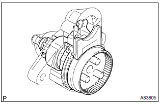
Toyota Corolla (E120): Overhaul
1. Remove repair service starter kit
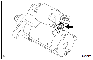
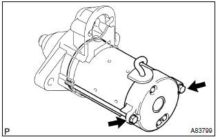
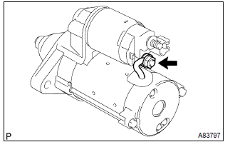
- Remove the nut, then disconnect the lead wire from terminal c.
- Remove the 2 screws which are used to secure the repair service starter kit to the starter drive housing.
- remove the repair service starter kit.
- remove the return spring and plunger from the starter drive housing.
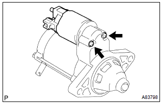
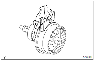
2. Remove starter yoke assy
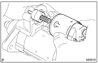
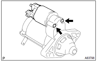
- Remove the 2 through bolts, then pull out the starter yoke together with the starter commutator end frame.
- Remove the starter yoke from the starter commutator end frame.
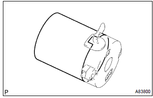
3. Remove starter armature plate
- Remove the starter armature plate from the starter yoke.
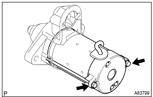
4. Remove starter commutator end frame cover
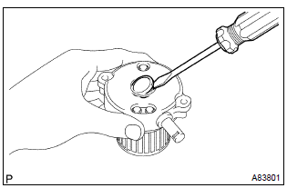
- Using a screwdriver, remove the starter commutator end frame cover.
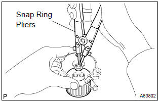
5. Remove starter armature assy
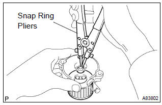
- Using snap ring pliers, remove the snap ring.
- remove the washer and starter armature from the starter commutator end frame.
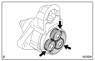
6. Remove planetary gear
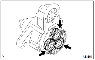
- Remove the 3 planetary gears from the starter center bearing clutch.
7. Remove starter center bearing clutch sub–assy
- Remove the starter center bearing clutch together with the starter drive lever set pin from the starter drive housing.
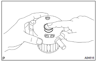
8. Remove starter drive lever set pin
- Remove the starter drive lever set pin from the starter center bearing clutch.
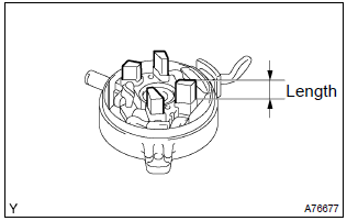
9. Inspect repair service starter kit
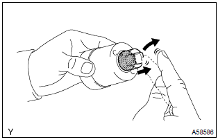
- Check the operation.
- Push in the plunger, then check that it returns quickly to its original position.
If necessary, replace the repair service starter kit.
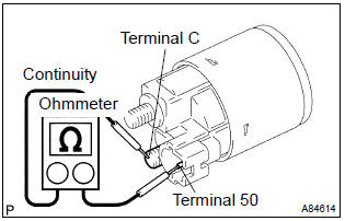
- Check the continuity.
- Using an ohmmeter, check that there is continuity between terminals 50 and c.
If there is no continuity, replace the repair service starter kit.
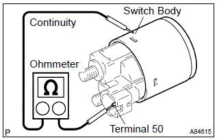
- Using an ohmmeter, check that there is continuity between terminal 50 and the switch body.
If there is no continuity, replace the repair service starter kit.
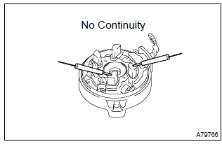
10. Inspect starter armature assy
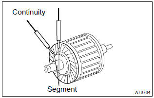
- Check the continuity.
- Using an ohmmeter, check that there is continuity
between the segments of the commutator.
If there is no continuity between any segments, replace the starter armature.
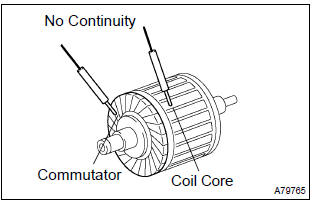
- Using an ohmmeter, check that there is no continuity between the commutator and armature coil core.
If there is continuity, replace the starter armature.
- check the commutator surface for dirt or burn.
If the surface is dirty or burnt, smooth the surface with 400–grit sandpaper or lathe.
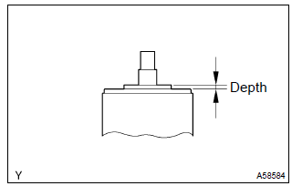
- Check the commutator depth.
- Using vernier calipers, measure the commutator
depth.
Standard depth: 3.1 Mm (0.122 In.) Maximum depth: 3.8 Mm (0.150 In.)
If the depth is greater than maximum, replace the starter armature.
11. Inspect starter commutator end frame assy
- Check the brush length.
- Using vernier calipers, measure the brush length.
Standard length: 9.0 Mm (0.354 In.) Minimum length: 4.0 Mm (0.158 In.)
If the length is less than minimum, replace the starter commutator end frame.
- Check the continuity.
- Using an ohmmeter, check that there is no continuity between the positive (+) and negative (–) brush.
If there is continuity, repair or replace the starter commutator end frame.
12. Inspect starter center bearing clutch sub–assy
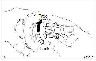
- Check the starter clutch.
- Rotate the clutch pinion gear clockwise, then check that it turns freely. Try to rotate the clutch pinion gear counterclockwise, then check that it locks.
If necessary, replace the starter center bearing clutch.
- Check the wear or damage.
- Inspect the gear teeth on the planetary gear, internal gear and starter clutch for wear or damage.
If damaged, replace the starter center bearing clutch.
13. Install starter drive lever set pin
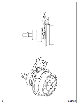
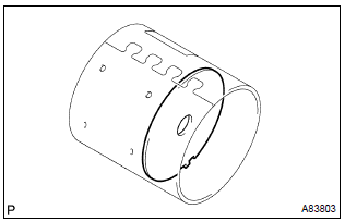
- Install the starter drive lever set pin to the starter center bearing clutch as shown in the illustration.
14. Install starter center bearing clutch sub–assy
- Install the starter center bearing clutch together with the starter drive lever set pin to the starter drive housing.
15. Install planetary gear
- Apply grease to the planetary gears and pin parts of the planetary shaft.
- install the 3 planetary gears to the starter center bearing clutch.
16. Install starter armature assy
- Apply grease to the washer and the armature shaft.
- install the starter armature and the washer to the starter commutator end frame.
- using snap ring pliers, install a new snap ring.
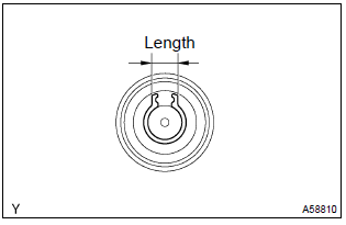
- Check the snap ring length.
- Using vernier calipers, measure the snap ring
length.
Maximum length: 5.0 Mm (0.197 In.)
If the length is greater than maximum, replace it with a new snap ring.
17. Install starter commutator end frame cover
- Install the starter commutator end frame cover to the starter commutator end frame.
18. Install starter armature plate
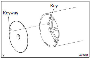
- Align the keyway of the starter armature plate with the key inside the starter yoke, then install the armature plate to the starter yoke.
19. Install starter commutator end frame assy
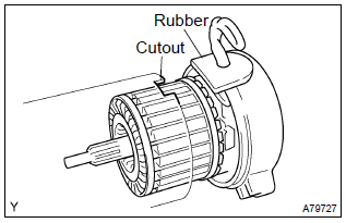
- Align the rubber with the cutout of the starter yoke, then install the starter commutator end frame to the starter yoke.
20. Install starter yoke assy
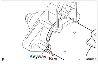
- Align the key of the starter yoke with the keyway of the starter drive housing, then install the starter yoke to the starter drive housing.
- Tighten the 2 through bolts.
Torque: 6.0 Nvm (61 Kgf·cm, 53 in.Vlbf)
21. Install repair service starter kit
- Apply grease to the plunger and hook.
- hang the plunger hook of the repair service starter kit to the starter drive lever set pin.
- install the plunger and return spring.
- Install the repair service starter kit with the 2 screws.
Torque: 7.5 Nvm (76 Kgf·cm, 66 in.Vlbf)
- Connect the lead wire to terminal c with the nut.
Torque: 10 nvm (102 Kgf·cm, 7 ft·lbf)


Other materials:
Deleting a registered phone number
1 Select “Delete contacts” using .
2 Select the desired phone number using
and press
(YES).
To delete all of the registered phone numbers, select “All delete” using
and press
(YES). ...
Circuit description
Refer to dtc p0115
Dtc no.
Dtc detection condition
Trouble area
P0125
If the engine coolant temperature (ect) was less than –6.6 °C
(20 °F) when starting the engine, and 20 minutes after the engine
start, the ect sensor still indicates below 20 °C (68 ...
Inspection procedure
Hint:
hand–held tester only:
narrowing down the trouble area is possible by performing ”a/f control” active
test (heated oxygen
sensor or other trouble areas can be distinguished).
Perform active test using hand–held tester (a/f control).
Hint:
”a/f control” is the active te ...