Toyota Corolla (E120): Overhaul
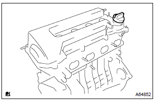
1. Remove oil filler cap sub–assy
- Remove the oil filler cap from the cylinder head cover.
2. Remove oil filler cap gasket
- Using a screwdriver, remove the gasket from the oil filler cap.
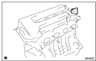
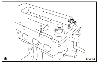
3. Remove ventilation valve sub–assy
- Remove the ventilation valve from the cylinder head cover.
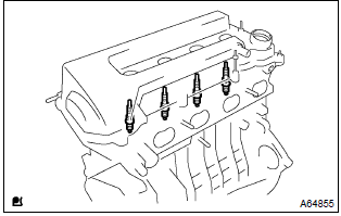
4. Remove spark plug
- Using a spark plug wrench, remove the spark plugs.
5. Remove cylinder head cover sub–assy
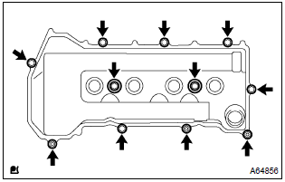
- Remove the 9 bolts, 2 seal washers, 2 nuts and cylinder head cover.
6. Remove cylinder head cover gasket
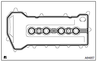
- Remove the gasket from the cylinder head cover.
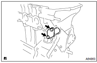
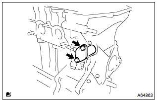
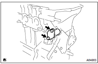
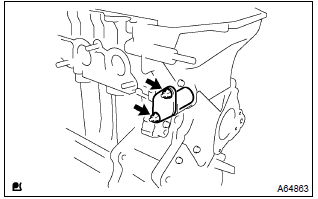
7. Remove transverse engine engine mounting bracket
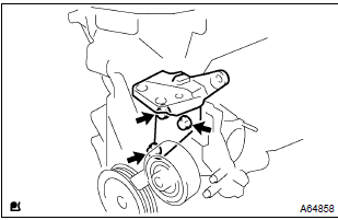
- Remove the 3 bolts and transverse engine engine mounting bracket.
8. Remove water pump assy
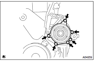
- Remove the 6 bolts and water pump.
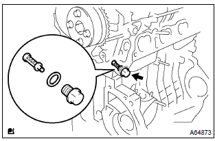
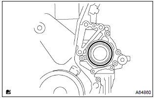
9. Remove water pump o–ring
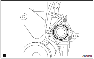
- Remove an o–ring from the timing chain cover.
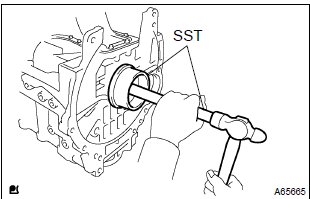
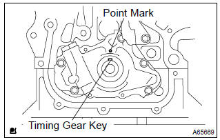
10. Remove crankshaft pulley
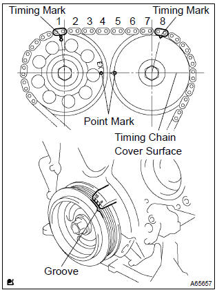
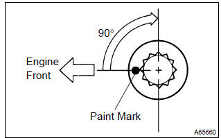
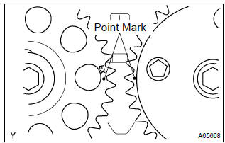
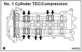
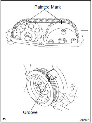
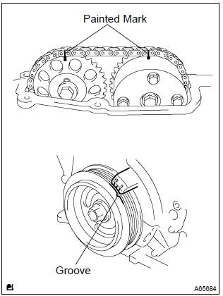
- Set the no. 1 Cylinder to the tdc/compression.
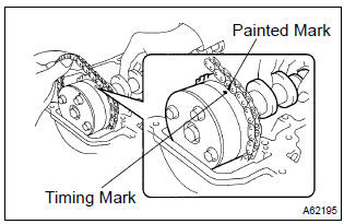
- Turn the crankshaft pulley, and align its groove with timing mark ”0” of the timing chain cover.
- Check that the point marks of the camshaft timing gears are in straight line on the timing chain cover surface as shown in the illustration.
Hint
: if not, turn the crankshaft 1 revolution (360 ) and align the marks as above.
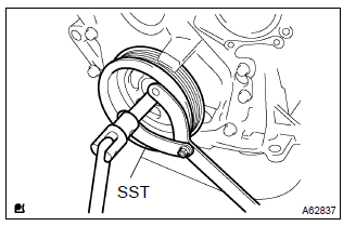
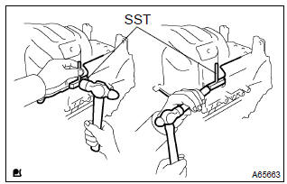
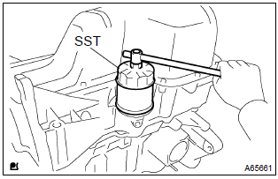
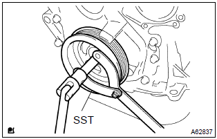
- Using sst, remove the crankshaft pulley bolt.
Sst 09960–10010 (09962–01000, 09963–01000)
- remove the crankshaft pulley from the crankshaft.
11. Remove chain tensioner assy no.1
- Remove the 2 nuts and chain tensioner.
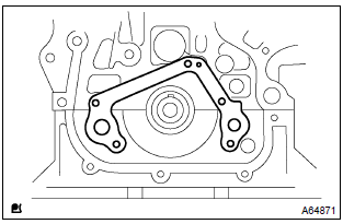
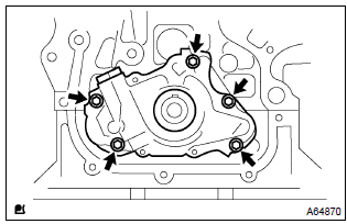
12. Remove timing chain or belt cover sub–assy
- Remove the 11 bolts and nut.
- remove the timing chain cover by prying the portions between the timing chain cover and cylinder head and cylinder block with a screwdriver.
Notice
: be careful not to damage the contact surfaces of the timing chain cover, cylinder head and cylinder block.
- Using a torx socket wrench e5, remove the 3 stud bolts.
13. Remove timing chain or belt cover oil seal
- Place the timing chain cover on wooden blocks.
- using a screwdriver, remove the oil seal.
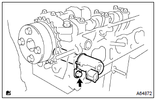
14. Remove crankshaft position sensor plate no.1

- Remove the crankshaft position sensor plate from the crankshaft.
15. Remove chain tensioner slipper
- Remove the bolt and chain tensioner slipper
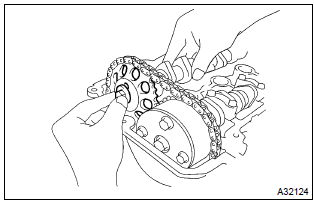
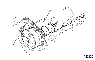
16. Remove chain sub–assy
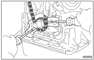
- Using the 2 screwdrivers, pry out the chain with the crankshaft timing gear as shown in the illustration.
Notice
:
- put shop rag to protect the engine.
- In case of revolving the camshafts with the chain off the gears, turn the crankshaft 1/4 revolution for valves not to touch the pistons.
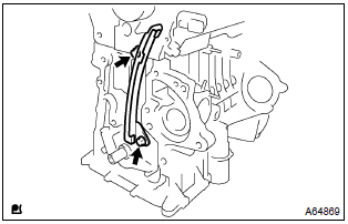
17. Remove chain vibration damper no.1
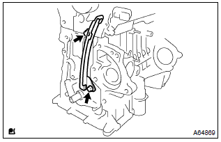
- Remove the 2 bolts and chain vibration damper.
18 Remove the 2 bolts and chain vibration damper.
- Remove the 5 bolts and oil pump.
19. Remove oil pump gasket
- Remove the gasket from the cylinder block.
20. Remove camshaft timing oil control valve assy
- Remove the bolt and camshaft timing oil control valve.
21. Remove oil control valve filter
- Remove the bolt with gasket and oil control valve filter.
- remove the gasket and oil control valve filter from the bolt.
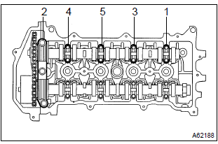
22. Remove camshaft
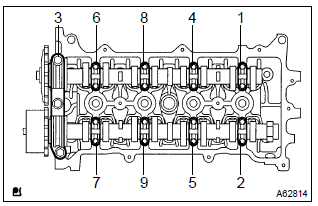
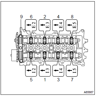
- Using several steps, uniformly loosen and remove the 19 bolts in the sequence shown, then remove the 9 bearing caps.
- remove the 2 camshafts from the cylinder head.
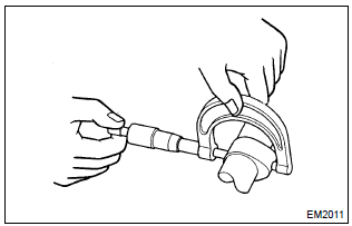
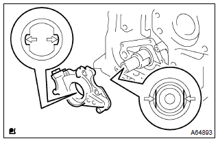
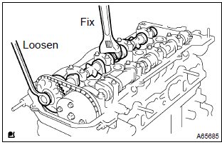
23. Remove camshaft timing gear or sprocket
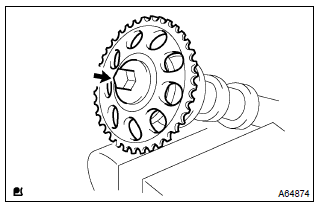
- Grip the camshaft with a vice, and remove the bolt and camshaft timing gear.
Notice
: be careful not to damage the camshaft.
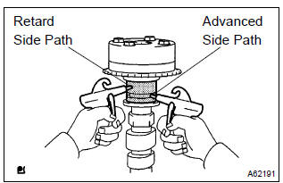
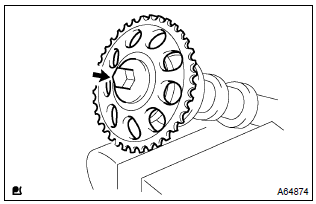
24. Inspect camshaft timing gear assy
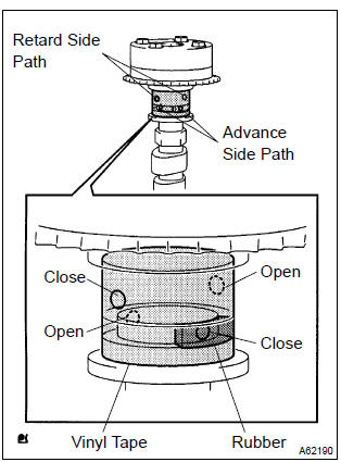
- Check the lock of camshaft timing gear.
- Clamp the camshaft in a vise, and confirm the camshaft timing gear is locked.
Notice
: be careful not to damage the camshaft.
- release the lock pin.
- Cover the 4 oil paths of the cam journal with vinyl tape as shown in the illustration.
Hint
: two advance side paths are provided in the groove of the camshaft.
Plug one of the path with a rubber piece.
- Break through the tapes of the advance side path and retard side path on the opposite side of the groove.
- Put air pressure into two broken paths (the advance side path and retard side path) with about 150 kpa {1.5 Kgf·cm2}.
Caution
: cover the paths with shop rag to avoid oil splashing.
- Confirm if the camshaft timing gear assembly revolves to the timing advance direction when weakening the air pressure of the timing retard path.
Hint
: the lock pin is released, and camshaft timing gear revolves to the advance direction.
- When the camshaft timing gear comes to the most advanced position, take out the air pressure of the timing retard side path, then take out that of the timing advance side path.
Caution
: the camshaft timing assembly gear occasionally shifts to the retard side abruptly, if the air compression of the advanced side path is released before the retard side path. It often causes the breakage of the lock pin.
- Check smooth revolution.
- Revolve the camshaft timing gear assembly within the movable range except for the most retarded position several times, and check that it revolves smoothly.
Caution
: be sure to perform this check by hand, instead of air pressure.
- check the lock in the most retarded position.
- Confirm that the camshaft timing gear assembly is locked at the most retarded position.
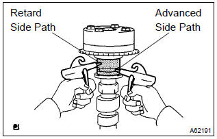
25. Remove camshaft timing gear assy
- Clamp the camshaft in a vise, and confirm that the gear is locked.
Caution
: be careful not to damage the camshaft.
- cover the 4 oil paths of the cam journal with vinyl tape as
shown in the illustration.
Hint
: two advance side paths are provided in the groove of the camshaft.
Plug one of the path with a rubber piece.
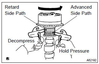
- break through the tapes of the advance side path and retard side path on the opposite side of the groove.
- Put air pressure into two broken paths (the advance side path and retard side path) with about 150 kpa {1.5 Kgf/ cm2}.
Caution
: cover the paths with shop rag to avoid oil splashing.
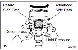
- Confirm if the camshaft timing gear assembly revolves to
the timing advance direction when weakening the air
pressure of the timing retard path.
Hint
: the lock pin is released, and camshaft timing gear revolves to the advance direction.
- when the camshaft timing gear comes to the most advanced
position, take out the air pressure of the timing retard
side path, then take out that of timing advance side
path.
Caution
: camshaft timing gear assembly occasionally shifts to the retard side abruptly, if the air compression of the advanced side path is released before the retard side path. It often causes the breakage of the lock pin.
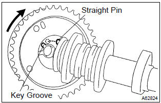
- remove the fringe bolt and camshaft timing gear.
Notice
:
- be sure not to remove the other 4 bolts.
- In case of reusing the camshaft timing gear, release the straight pin locking first, then install the gear.
26. Remove cylinder head sub–assy
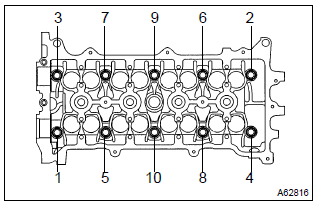
- Using a bi–hexagon wrench 10, uniformly loosen and remove the 10 cylinder head bolts, in several passes, in the sequence shown, then remove the 10 cylinder head bolts and 10 plate washers.
Notice
:
- be careful not to drop plate washers into the cylinder head.
- Head warpage or cracking could result from removing bolts in an incorrect order.

- Remove the cylinder head from the cylinder block.
27. Remove cylinder head gasket
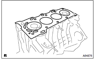
- Remove the cylinder head gasket from the cylinder block.
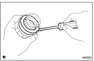
28. Remove oil filter sub–assy

- Using sst, remove the oil filter.
Sst 09228–06501
29. Remove oil filter union
- Using a socket hexagon wrench 12, remove the oil filter union.
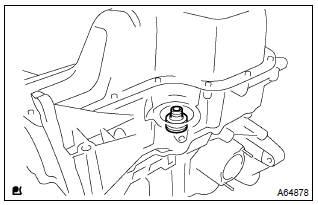
30. Remove engine rear oil seal
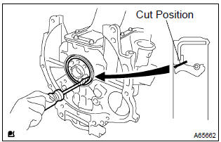
- Using a knife, cut off the oil seal lip.
- using a screwdriver with the tip wrapped in tape, pry out the oil seal.
Notice
: after the removal, check if the crankshaft is not damaged.
If damaged, smooth it with a 400–grid sandpaper.
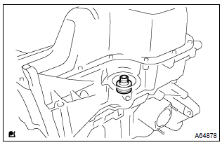
31. Remove oil pan drain plug
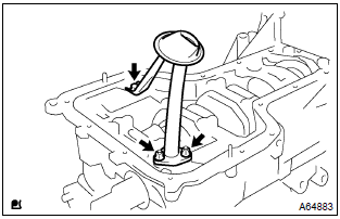
- Remove the oil pan drain plug and gasket from the oil pan.
32. Remove oil pan sub–assy
- Remove the 14 bolts and 2 nuts.
- Insert the blade of sst between the bearing cap and oil
pan, then cut off the applied sealer and remove the oil
pan.
Sst 09032–00100
N
otice
: be careful not to damage the oil pan contact surface of the bearing cap and oil pan.
33. Remove oil strainer sub–assy
- Remove the bolt, 2 nuts and oil strainer.
34. Remove oil strainer flange gasket
- 34. Remove oil strainer flange gasket
35. Inspect chain tensioner assy no.1
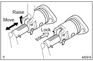
- Check that the plunger moves smoothly when the ratchet pawl is raised with your finger.
- release the ratchet pawl and check that the plunger is locked in place by the ratchet pawl and does not move when pushed with your finger.
36. Inspect chain sub–assy
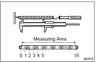
- Using a spring tension gauge and vernier caliper, pull the timing chain with 140 n (14.3 Kgf, 31.5 Lb) and measure the length of it.
Maximum chain elongation: 122.6 Mm (4.827 In.) If the chain elongation is greater than maximum, replace the chain.
Hint
: make the same measurements pulling at 3 or more places selected at random.
37. Inspect camshaft timing gear or sprocket
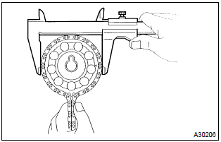
- Wrap the chain around the camshaft timing gear.
- using a vernier caliper, measure the camshaft timing gear
diameter with the chain.
Minimum gear diameter (w/ chain): 97.3 Mm (3.831 In.)
Notice
: the vernier caliper must contact the chain rollers for measuring.
If the gear diameter is less than minimum, replace the chain and camshaft timing gear.
38. Inspect crankshaft timing gear or sprocket
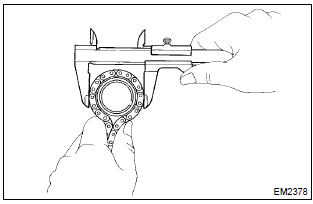
- Wrap the chain around the crankshaft timing gear.
- using a vernier caliper, measure the crankshaft timing
gear diameter with the chain.
Minimum gear diameter (w/ chain): 51.6 Mm (2.032 In.)
Notice
: the vernier caliper must contact the chain rollers for measuring.
If the gear diameter is less than minimum, replace the chain and crankshaft timing gear.
39. Inspect chain tensioner slipper
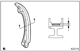
- Using a vernier caliper, measure the chain tensioner slipper
wears.
Maximum wear: 1.0 Mm (0.039 In.)
If the wear is greater than maximum, replace the chain tensioner slipper.
40. Inspect chain vibration damper no.1
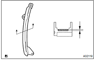
- Using a vernier caliper, measure the vibration damper
wears.
Maximum wear: 1.0 Mm (0.039 In.)
If the wear is greater than maximum, replace the chain vibration damper
41. Inspect cylinder head set bolt
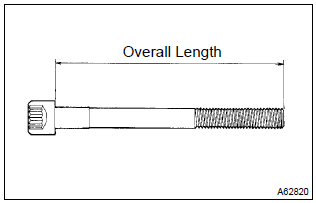
- Using a vernier caliper, measure the length of cylinder
head bolts from the seat to the end.
Standard bolt length: 146.8 To 148.2 Mm (5.780 To 5.835 In.) Maximum bolt length: 148.5 Mm (5.846 In.)
If the bolt length is greater than maximum, replace the cylinder head set bolt.
42. Inspect camshaft
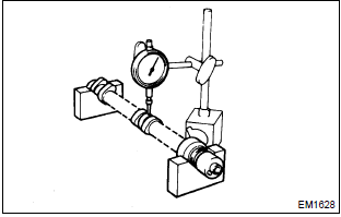
- Inspect the camshaft for runout.
- Place the camshaft on v–blocks.
- Using a dial indicator, measure the circle runout at
the center journal.
Maximum circle runout: 0.03 Mm (0.0012 In.)
If the circle runout is greater than maximum, replace the camshaft.
- Inspect the cam lobes.
- Using a micrometer, measure the cam lobe height.
Standard cam lobe height: 44.333 To 44.433 Mm (1.7454 To 1.7493 In.) For intake 43.761 To 43.861 Mm (1.7229 To 1.7268 In.) For exhaust minimum cam lobe height: 44.18 Mm (1.7394 In.) For intake 43.61 Mm (1.7169 In.) For exhaust
If the cam lobe height is less than minimum, replace the camshaft.
- Inspect the camshaft journals.
- Using a micrometer, measure the journal diameter.
No. 1 Journal diameter: 34.449 To 34.465 Mm (1.3563 To 1.3569 In.) Others journal diameter: 22.949 To 22.965 Mm (0.9035 To 0.9041 In.)
If the journal diameter is not as specified, check the oil clearance.
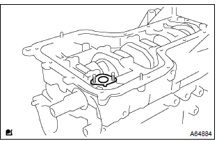
43. Install oil strainer flange gasket
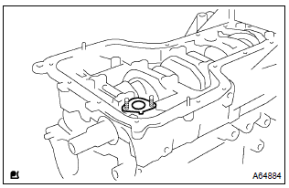
- Install a new gasket to the bearing cap.
44. Install oil strainer sub–assy
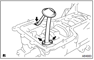
- Install the oil strainer with the 2 nuts and bolt.
Torque: 9.0 Nvm (92 Kgf·cm, 80 in.Vlbf)
45. Install oil pan sub–assy
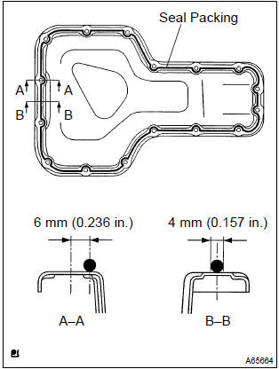
- Remove any old packing material from the contact surface and thread holes.
- apply the seal packing in the shape of the bead (diameter
3.5 Mm to 4.5 Mm (0.138 To 0.177 In.)) Consequently as
shown in the illustration.
Seal packing: part no. 08826–00080 Or equivalent
Notice
:
- remove any oil from the contact surface.
- Install the oil pan within 3 minutes after applying the seal packing.
- Do not put into engine oil within 2 hours of installation.
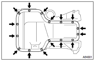
- Install the oil pan with the 14 bolts and 2 nuts.
Torque: 9.0 Nvm (92 Kgf·cm, 80 in.Vlbf)
46. Install oil pan drain plug

- Place a new gasket on the oil pan drain plug, and install
it.
Torque: 37 nvm (377 Kgf·cm, 27 ft·lbf)
47. Install engine rear oil seal
- Apply a light coat of multi–purpose grease to a new oil
seal lip.
Notice
: keep the lip off foreign materials.
- using sst, tap in the oil seal until its surface is flush with
the oil seal retainer edge.
Sst 09223–15020, 09950–70010 (09951–07100)
N
otice
: wipe off extra grease on the crankshaft.
48. Install oil filter union
- using a socket hexagon wrench 12, install the oil filter
union.
Torque: 30 nvm (306 Kgf·cm, 22 ft·lbf)
49. Install oil filter sub–assy
- Check and clean the oil filter installation surface.
- apply clean engine oil to the gasket of a new oil filter
- lightly screw the oil filter into place, and tighten it until the gasket contacts the seat.
- using sst, tighten it an additional 3/4 turn.
Sst 09228–06501
50. Install cylinder head gasket
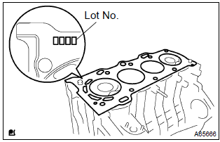
- Place a new cylinder head gasket on the cylinder block surface with the lot no. Stamp upward.
Notice
: pay attention to the installation direction.
Place the cylinder head gently in order not to damage the gasket with the bottom part of the head.
51. Install cylinder head sub–assy
- Place the cylinder head on the cylinder block.
- apply a light coat of engine oil on the threads and under the heads of the cylinder head bolts.
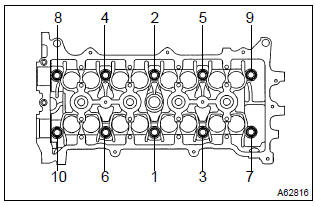
- Using a bi–hexagon wrench 10, install and uniformly tighten
the 10 cylinder head bolts with the plate washers, in
several passes, in the sequence shown.
Torque: 49 nvm (500 Kgf·cm, 36 ft·lbf)
- Mark the front of the cylinder head bolt with paint.
- retighten the cylinder head bolts 90 in the numerical order shown.
- check that the point marked bolts are moved by 90 angle.
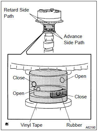
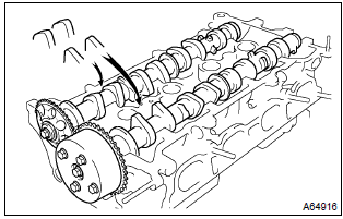
52. Install camshaft timing gear assy
- Put the camshaft timing gear assembly and camshaft together with the straight pin off the key groove.
- turn the camshaft timing gear assembly to the left direction
(as shown in the illustration) with pushing it lightly
against the camshaft. Push further at the position where
the pin gets into the groove.
Caution
: be sure not to turn the camshaft timing gear to the retard angle side (to the right angle).
- check that there is no clearance between the gear’s fringe and camshaft.
- tighten the fringe bolt with the camshaft timing gear fixed.
Torque: 54 nvm (551 Kgf·cm 40 ft·lbf)
- check that the camshaft timing gear assembly can move to the retard angle side (the right angle), and is locked at the most retarded position.
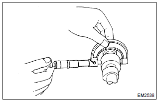
53. Install camshaft timing gear or sprocket
- Grip the camshaft with a vise, then install the camshaft
timing gear with the bolt.
Torque: 54 nvm (551 Kgf·cm 40 ft·lbf)
Notice
: be careful not to damage the camshaft.
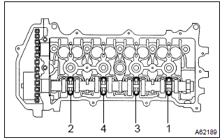
54. Install camshaft
- Apply a light coat of engine oil on the camshaft journals.
- place the 2 camshafts on the cylinder head with the no.
1 Cam lobes facing as shown the illustration.
- Examine the front marks and numbers, then tighten the
bolts in the order shown in the illustration.
Torque:
23 nvm (235 Kgf·cm, 17 ft·lbf) for bearing cap no. 1 13 Nvm (133 Kgf·cm, 10 ft·lbf) for bearing cap no. 3
55. Install oil control valve filter
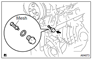
- Check that no foreign substance on the mesh part of the oil control valve filter.
- install a new gasket and the oil control valve filter on the
bolt, then install it.
Torque: 30 nvm (306 Kgf·cm, 22 ft·lbf)
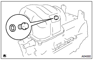
56. Install camshaft timing oil control valve assy
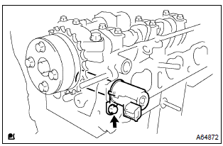
- Apply a light coat of engine oil to a new o–ring, then install it to the camshaft timing oil control valve.
- install the camshaft timing oil control valve with the bolt.
Torque: 9.0 Nvm (92 Kgf·cm, 80 in.Vlbf)
N
otice
: be careful not twist the o–ring.
57. Install oil pump gasket
- Install a new gasket to the cylinder block.
58. Install oil pump assy
- Engage the spline teeth of the oil pump drive rotor with the large teeth of the crankshaft, and side the oil pump into place.
- Install the oil pump with the 5 bolts.
Torque: 9.0 Nvm (92 Kgf·cm, 80 in.Vlbf)
59. Install chain vibration damper no.1
- Install the chain vibration damper with the 2 bolts.
Torque: 9.0 Nvm (92 Kgf·cm, 80 in.Vlbf)
60. Install chain sub–assy
- Set the no. 1 Cylinder to the tdc/compression.
- Turn the hexagonal wrench head portion of the camshafts, then align the point marks of the camshaft timing gears.
- Using a crankshaft pulley bolt, turn the crankshaft to align the timing gear key with the point mark located on the oil pump.
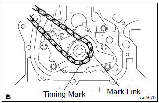
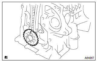
- Install the chain on the crankshaft timing gear with the yellow color mark link aligned with the timing mark on the crankshaft timing gear.
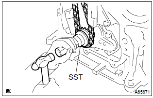
- Using sst, install the crankshaft timing gear.
Sst 09223–22010
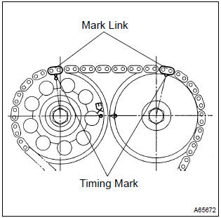
- Install the chain on the camshaft timing gears with the yellow color mark links aligned with the timing marks on the camshaft timing gears.
61. Install chain tensioner slipper
- Install the chain tensioner slipper with the bolt.
Torque: 19 nvm (189 Kgf·cm, 14 ft·lbf)
62. Install crankshaft position sensor plate no.1
- Install the crankshaft position sensor plate with the ”f” mark facing forward.
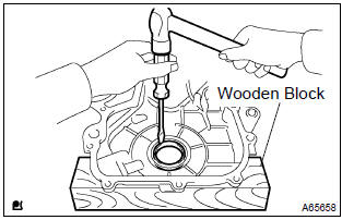
63. Install timing chain or belt cover oil seal
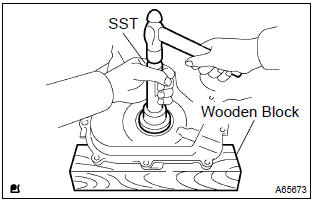
- Apply a light coat of multi–purpose grease to a new oil seal lip.
- place the timing chain cover on wooden blocks.
- using sst, tap in the oil seal until its surface is flush with
the timing chain cover edge.
Sst 09223–22010
Notice
: keep the lip free off foreign materials.
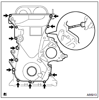
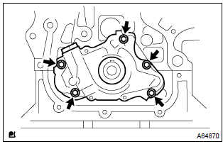
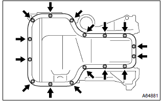
64. Install timing chain or belt cover sub–assy
- Remove any old packing material from the contact surface.
- using a torx socket wrench e5, install the 3 stud bolts.
Torque: 5.0 Nvm (51 Kgf·cm, 44 in.Vlbf)
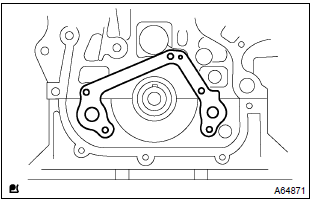
- Apply a continuous bead (3.5 To 4.5 Mm (0.138 To 0.177
In.) Diameter) of seal packing as shown in the illustration.
Seal packing:
water pump part: part no. 08826–00100 Or equivalent other part: part no. 08826–00080 Or equivalent
N
otice
:
- remove any oil from the contact surface.
- Install the oil pan within 3 minutes after applying the seal packing.
- Do not put into engine oil within 2 hours of installation.
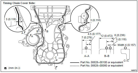
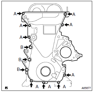
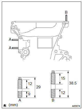
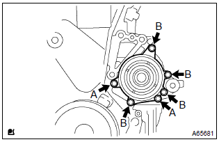
- Install the timing chain cover with the 12 bolts and nut.
Torque:
13 nvm (133 Kgf·cm, 10 ft·lbf) for bolt a and nut a 19 nvm (189 Kgf·cm, 14 ft·lbf) for bolt b
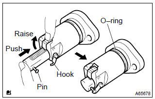
65. Install chain tensioner assy no.1
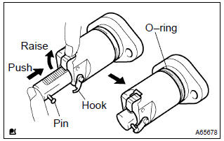
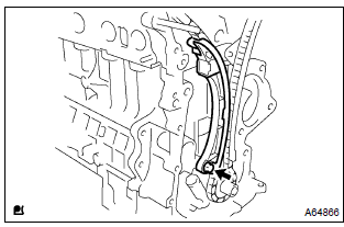
- Check the o–ring is clean, and set the hook as shown in the illustration.
- apply a light coat of engine oil to the o–ring.
- Install the chain tensioner with the 2 nuts.
Torque: 9.0 Nvm (92 Kgf·cm, 80 in.Vlbf)
N
otice
:
- be careful not twist the o–ring.
- When installing the chain tensioner, set the hook again if the hook releases the plunger.
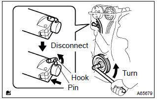
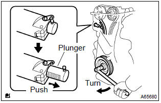
66. Install crankshaft pulley
- Align the pulley set key with the key groove of the crankshaft pulley, then slide on the crankshaft pulley.
- using sst, install the crankshaft pulley bolt.
Sst 09960–10010 (09962–01000, 09963–01000) torque: 138 nvm (1,407 Kgf·cm, 102 ft·lbf)
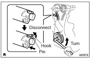
- Turn the crankshaft counterclockwise, then disconnect the plunger knock pin from the hook.
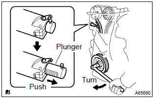
- Turn the crankshaft clockwise, then check that the slipper is pushed by the plunger.
Hint
: if the plunger does not spring out, press the slipper into the chain tensioner with a screwdriver so that the hook is released from the knock pin and that the plunger springs out.
67. Install water pump o–ring
- Install a new o–ring to the timing chain cover.
68. Install water pump assy
- Install the water pump with the 6 bolts.
Torque:
9.0 Nvm (92 Kgf·cm, 80 invlbf) for bolt a 11 nvm (112 Kgf·cm, 8 ft·lbf) for bolt b
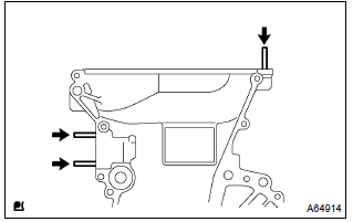
69. Install transverse engine engine mounting bracket
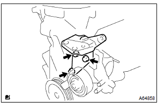
- Install the transverse engine engine mounting bracket
with the 3 bolts.
Torque: 47 nvm (479 Kgf·cm, 35 ft·lbf)
70. Inspect valve clearance
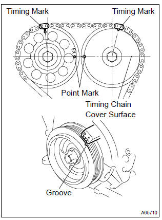
- Set the no. 1 Cylinder to the tdc/compression.
- Turn the crankshaft pulley, and align its groove with timing mark ”0” of the timing chain cover.
- Check that the point marks of the camshaft timing gears are in straight line on the timing chain cover surface as shown in the illustration.
Hint
: if not, turn the crankshaft 1 revolution (360 ) and align the marks as above.
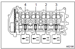
- Check only the valves indicated.
- Using a feeler gauge, measure the clearance between the valve lifter and camshaft.
- Record the out–of specification valve clearance
measurements. They will be used later to determine
the required replacement valve lifters.
Valve clearance (cold): 0.15 To 0.25 Mm (0.0059 To 0.0098 In.) For intake 0.25 To 0.35 Mm (0.0098 To 0.0138 In.) For exhaust
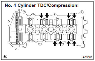
- Turn the crankshaft 1 revolution (360 ) and set no. 4 The cylinder to the tdc/compression.
- check only the valves indicated.
- Using a feeler gauge, measure the clearance between the valve lifter and camshaft.
- Record the out–of specification valve clearance
measurements. They will be used later to determine
the required replacement valve lifters.
Valve clearance (cold): 0.15 To 0.25 Mm (0.0059 To 0.0098 In.) For intake 0.25 To 0.35 Mm (0.0098 To 0.0138 In.) For exhaust
71. Adjust valve clearance
Notice
: be sure not to revolve the crankshaft without the chain tensioner.
- set the no. 1 Cylinder to the tdc/compression.
- place the painted marks on the chain and camshaft timing gears.
- Remove the 2 nuts and chain tensioner.
- Fix the camshaft with a spanner and so on, then loosen the camshaft timing gear set bolt.
Notice
: be careful not to damage the valve lifter.
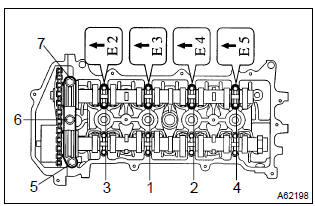
- Loosen the bearing cap bolts on the no. 2 Camshaft in the order as shown in the illustration in several passes, then remove the bearing caps.
- Remove the camshaft timing gear as shown in the illustration.
- Loosen the bearing cap bolts on camshaft in the order as shown in the illustration in several passes, then remove the bearing caps.
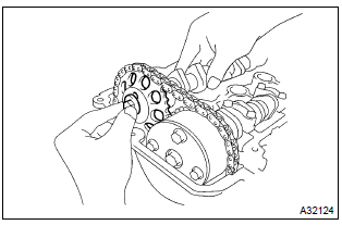
- Remove the camshaft while holding the chain.
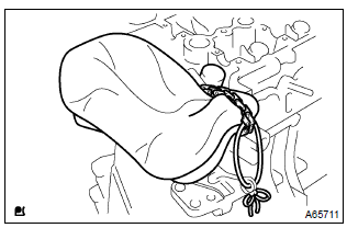
- Tie the chain with a string as shown in the illustration.
Notice
: be careful not to drop anything inside the timing chain cover.
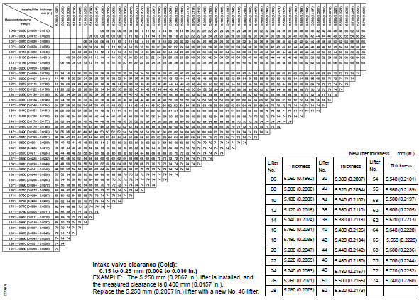
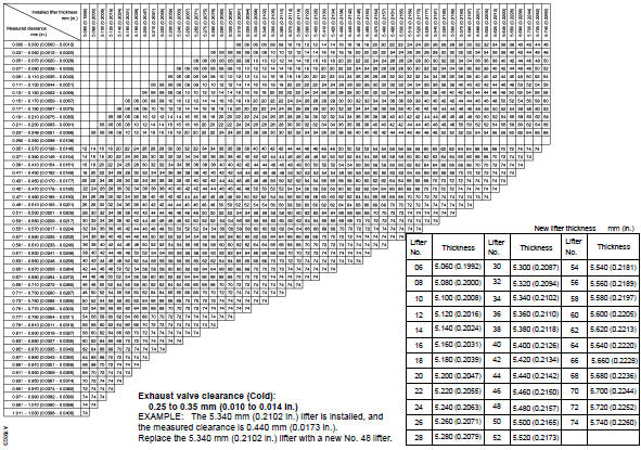
- remove the valve lifters.
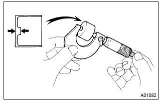
- Using a micrometer, measure the thickness of the removed valve lifters.
- calculate the thickness of a new lifter so that the valve clearance comes within the specified value.
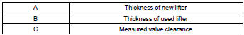
Valve clearance:
intake a = b + (c – 0.20 Mm (0.0079 In.))
Exhaust a = b + (c – 0.30 Mm (0.0118 In.))
| Example (intake): measure intake valve clearance = 0.40 Mm (0.0158 In.) 0.40 Mm (0.0158 In.) – 0.20 Mm (0.0079 In.) = 0.20 Mm (0.0079 In.) (Measured – specification = excess clearance) used lifter measurement = 5.250 Mm (0.2067 In.) 0.20 Mm (0.0079 In.) + 5.250 Mm (0.2067 In.) = 5.450 Mm (0.2146 In.) (Excess clearance + used lifter = ideal new lifter) closest new lifter = 5.460 Mm (0.2150 In.) Select no. 46 Lifter |
Hint
:
- select a new lifter with a thickness as close as possible to the calculated values.
- Lifter are available in 35 sizes in increments of 0.020 Mm (0.0008 In.), From 5.060 Mm (0.1992 In.) To 5.740 Mm (0.2260 In.).
- Refer to new lifter thickness table on the next 2 pages.
Valve lifter selection chart (intake)
Valve lifter selection chart (exhaust)
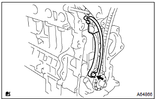
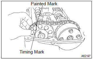
- As shown in the illustration, install the chain on the camshaft timing gear with the painted mark aligned with the timing mark on the camshaft timing gear.
- Examine the front marks and numbers, then tighten the
bolts in the order shown in the illustration.
Torque: 13 nvm (133 Kgf·cm, 10 ft·lbf)
- Put the camshaft no. 2 On the cylinder head with the painted mark of the chain aligned with the timing mark on the camshaft timing gear.
- Raise the camshaft, then tighten the set bolt temporarily.
- Examine the front marks and numbers, then tighten the
bolts in the order shown in the illustration.
Torque:
23 nvm (235 Kgf·cm, 17 ft·lbf) for bearing cap no. 1 13 Nvm (133 Kgf·cm, 10 ft·lbf) for bearing cap no. 3
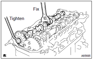
- Fix the camshaft with a spanner and so on, then tighten
the camshaft timing gear set bolt.
Torque: 54 nvm (551 Kgf·cm, 40 ft·lbf)
N
otice
: be careful not to damage the valve lifte
- Check the painted marks on the chain and camshaft timing gears. Then, check that the crankshaft pulley groove and the timing mark of the timing chain cover are aligned as shown in the illustration.
- Install the chain tensioner.
- Check the o–ring is clean, and set the hook as shown in the illustration.
- Apply a light coat of engine oil to the o–ring.
- Install the chain tensioner with the 2 nuts.
Torque: 9.0 Nvm (92 Kgf·cm, 80 invlbf)
N
otice
:
- be careful not twist the o–ring.
- When installing the tensioner, set the hook again if the hook releases the plunger.
- Turn the crankshaft counterclockwise, then disconnect the plunger knock pin from the hook.
- Turn the crankshaft clockwise, then check that the slipper is pushed by the plunger.
Hint
: if the plunger does not spring out, press the slipper into the chain tensioner with a screwdriver so that the hook is released from the knock pin and that the plunger springs out.
72. Install cylinder head cover gasket
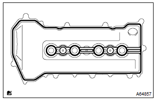
- Install the gasket to the cylinder head cover.
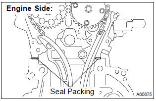
73. Install cylinder head cover sub–assy
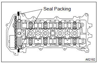
- Remove any old packing (fipg) material.
- apply the seal packing to the 2 locations as shown in the
illustration.
Seal packing: part no. 08826–00080 Or equivalent
N
otice
:
- remove any oil from the contact surface.
- Install the cylinder head cover within 3 minutes after applying the seal packing.
- Do not put into engine oil 2 hours of installation.
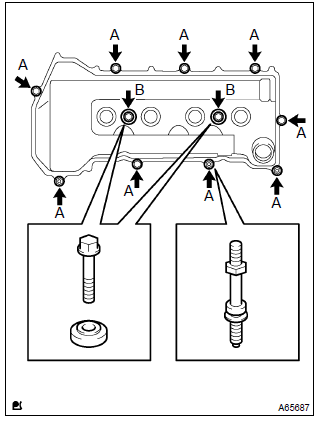
- Install the cylinder head cover with the 9 bolts, 2 seal
washers and 2 nuts.
Torque:
11 nvm (112 Kgf·cm, 8 ft·lbf) for bolt a and nut a 9.0 Nvm (92 Kgf·cm, 80 invlbf) for bolt b
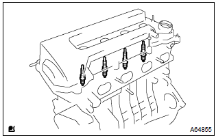
74. Install spark plug
- Using a spark plug wrench, install the spark plugs.
Torque: 25 nvm (255 Kgf·cm, 18 ft·lbf)
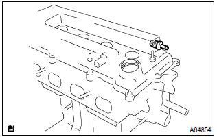
75. Install ventilation valve sub–assy
- Install the ventilation valve to the cylinder head cover.
Torque: 30 nvm (306 Kgf·cm, 22 ft·lbf)
76. Install oil filler cap gasket
- Install the gasket to the oil filler cap.
77. Install oil filler cap sub–assy
- Install the oil filler cap to the cylinder head cover.


Other materials:
Tire size
■ Typical tire size information
The illustration indicates typical tire size.
1 Tire use (P = Passenger car, T = Temporary use)
2 Section width (millimeters)
3 Aspect ratio (tire height to section width)
4 Tire construction code (R = Radial, D = Diagonal)
5 Wheel diameter (inches)
6 Loa ...
Confirmation driving pattern
Connect the hand–held tester or the obd ii scan tool to the dlc3.
record dtcs and the freeze frame data.
set the check mode using the hand–held tester .
read the value on the misfire counter for each cylinder when
idling. If the value is displayed on the
misfire c ...
Turning on light switch does not light up night time
illumination of radio receiver
Wiring diagram
Inspection procedure
1 Inspect radio receiver assy(ill+, ill–)
Check that the voltage between terminals at each condition,
as shown in the chart.
Standard:
Repair or replace harness or connector ...