
Toyota Corolla (E120) 2002–2008 Repair Manual / Diagnostics / Sfi system / Evaporative emission control
system pressure sensor / Monitor description
Toyota Corolla (E120): Monitor description
Dtc p0451, p0452 or p0453 is recorded by the ecm when the vapor pressure sensor malfunctions.
P0451
The ecm senses pressure in the fuel tank using the vapor pressure sensor. The ecm supplies the sensor with a regulated 5 v reference–voltage and the sensor returns a signal voltage between 0.5 V and 4.5 V according to the pressure level in the fuel tank.
When the pressure in the fuel tank is low, the output voltage of the vapor pressure sensor is low. When it is high, the output voltage is high.
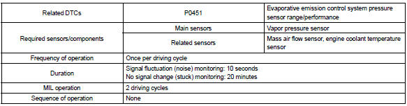
For this dtc p0451, the ecm checks for a ”noisy” sensor or a ”stuck” sensor.
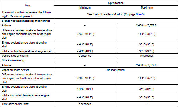
The ecm checks for the ”noisy” sensor by monitoring the fuel tank pressures when the vehicle is stationary and there should be little variation in the tank pressure. If the indicated pressure varies beyond specified limits, the ecm will illuminate the mil and a dtc is set.
The ecm checks for the ”stuck” sensor by monitoring the fuel tank pressure for an extended time period.
If the indicated pressure does not change over this period, the ecm will conclude that the fuel tank pressure sensor is malfunctioning. The ecm will illuminate the mil and a dtc is set.
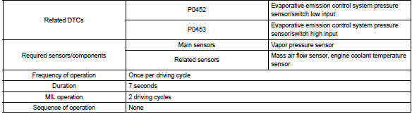
P0452 and p0453
The ecm senses pressure in the fuel tank using the vapor pressure sensor. The ecm supplies the sensor with a regulated 5 v reference–voltage and the sensor returns a signal voltage between 0.5 V and 4.5 V according to the pressure level in the fuel tank.
When the pressure in the fuel tank is low, the output voltage of the vapor pressure sensor is low. When it is high, the output voltage is high.
If the output voltage of the vapor pressure sensor is out of the normal range, the ecm will determine that there is a malfunction in the sensor or sensor circuit.
When pressure indicated by the vapor pressure sensor deviates below –3.999 Kpa (–30 mmhg) or above 1.999 Kpa (15 mmhg), the ecm interprets this as a malfunction in the vapor pressure sensor. The ecm will turn on the mil and a dtc will be set.
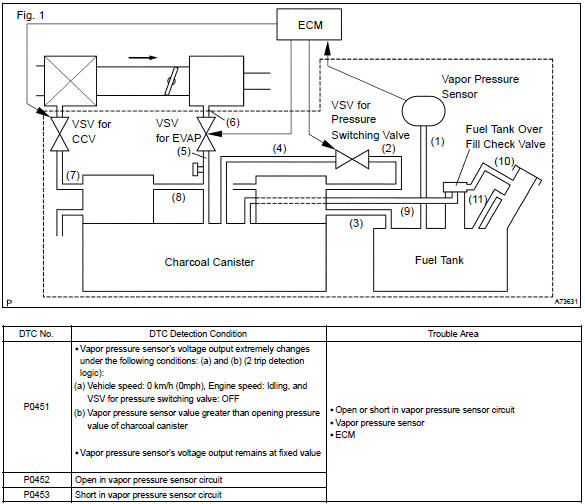
Monitor strategy
P0451
P0452 and p0453
Typical enabling conditions
P0451
P0452 and p0453
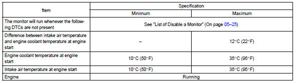
Typical malfunction thresholds
P0451
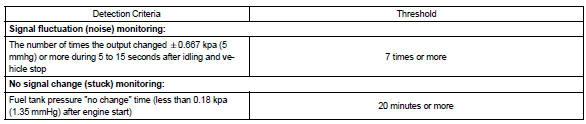
P0452 and p0453

Wiring diagram
Refer to dtc no. P0441


Other materials:
How to proceed with troubleshooting
1 Vehicle brought in
2 Customer problem analysis check and symptom check
3 Problem symptoms table
Without applicable symptoms, proceed to ”a”
with applicable symptoms, proceed to ”b”
4 Perform troubleshooting in the following method, depending on
malfunction symptom ...
Shift lock system (atm)
On–vehicle inspection
1. Check shift lock operation
shift the shift lever to p position.
turn the ignition switch to lock.
check that the shift lever cannot be shifted to any other
positions other than p.
turn the ignition switch to on, depress the brake pedal ...
Circuit description
The shift solenoid valve sl is turned ”on” and ”off” by signals from the ecm
in order to control the hydraulic
pressure operation, the lock–up relay valve, which then the controls operation
of the lock–up clutch.
Fail safe function:
if the ecm detects a malfunction, it turns the ...