Toyota Corolla (E140) 2007–2013 Body Repair Manual / Introduction / Introductions
Toyota Corolla (E140): Introductions
4. Anti-rust treatment after installation
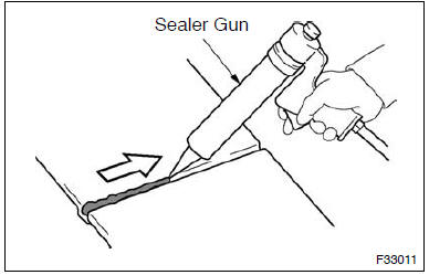
(A) body sealer application
Purpose: for water-proofing and anti-rust measures, always apply the body sealer to the body panel seams and hems of the doors, hood, etc.
Notice
: apply body sealer neatly to parts that require a high quality appearance.
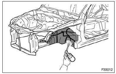
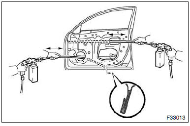
(B) undercort application
Purpose:
to prevent corrosion and protect the body from gravel, always apply a sufficient undercoating to the areas indicated.
(C) vehicle body anti-rust agent application
Purpose:
the purpose is to protect areas from rust which are difficult to paint such as the backside of the box-shaped cross section frame parts.
Method
: apply anti-rust agent through the service holes and/or installation holes of the parts.
5. Headlight bracket repair
Hint:
- if the installation area of the headlight assembly is damaged, use the supply retainer for low-cost repair.
- Ensure that the headlight assembly is not damaged.
(A) install upper headlight protector retainer
(1) cut off the part shaded in the illustration and smooth with sandpaper.
Notice
: after cutting off the part, place the upper headlight protector retainer against the bosses and gradually file away the old bracket if it interferes with the installation of the supply bracket.
(2) Install the upper headlight protector retainer with the 2 screws.
(B) install lower headlight protector retainer
(1) cut off the part shaded in the illustration and smooth with sandpaper.
Notice
: after cutting off the part, place the lower headlight protector retainer against the bosses and gradually file away the old bracket if it interferes with the installation of the supply bracket.
(2) Install the lower headlight protector retainer with the 2 screws.
(C) install lower headlight bracket
(1) cut off the part shaded in the illustration and smooth with sandpaper.
Notice
: after cutting off the part, place the lower headlight bracket against the bosses and gradually file away the old bracket if it interferes with the installation of the supply bracket.
(2) Install the lower headlight bracket with the 2 screws.
6. Procedures necessary when ecu or other parts are replaced
(a) the work list
(1) each inspection procedure refers to the toyota repair manual.
|
Replacement part |
Necessary procedure |
Effect/inoperative function when necessary procedures are not performed |
Note |
| Ecm | Vehicle identification number (vin) registration | Mil comes on | Using the techstream |
| Ecu commnication id registration |
|
— |
|
| Reset memory (*1) |
|
Using the techstream | |
|
Reset memory |
|
Using the intelligent tester |
| Tire pressure warning ecu |
|
|
— |
| Tire pressure warning valve and transmitter |
|
|
Even if only one wheel is replaced, ids for all 4 wheels must be registered |
| Brake actuator assembly (skid control ecu) | Perform yaw rate and acceleration sensor zero point calibration |
|
Perform yaw rate and acceleration sensor zero point calibration with the ignition switch on (engine stopped). |
|
|
|
Perform yaw rate and acceleration sensor zero point calibration with the ignition switch on (engine stopped) |
|
Perform rotation angle sensor initialization and torque sensor zero point calibration. |
|
Dtc (c1515/c1525) will be stored when the power steering ecu is replaced |
| Power steering ecu (*3) |
|
|
Dtc (c1515/c1525) will be stored when the power steering ecu is replaced |
| Steering column (*3) | Torque sensor zero point calibration | Steering effort is different between turning steering wheel to left and right |
— |
|
|
Wireless door lock control system | — |
| Steering lock actuator (steering lock ecu) (*4) | Ecu code registration | Engine start | — |
|
Key id registration |
|
— |
| Id code box (*4) |
|
|
— |
| Occupant classification ecu |
|
Occupant classification system passenger airbag on/off indicator airbag system (front passenger side) seat belt warning system (front passenger side) |
— |
|
Perform sliding roof drive gear reset. |
|
Necessary when removed and installed (not necessary when the sliding roof drive gear (sliding roof ecu) is removed and installed together with the sliding roof housing.) |
*1: For u341e, u250e automatic transaxle
*2: for 2az-fe
*3: for 2zr-feV
*4: w/ smart key systemV
*5: w/o smart key system


Other materials:
How to proceed with troubleshooting
1 Vehicle brought to workshop
2 Customer problem analysis
3 Problem symptom confirmation
4 Circuit inspection
5 Repair or replace
6 Confirmation test
7 End
Customer problem analysis check
...
Inspection and adjustment procedure
1 Tire valve
2 Tire pressure gauge
1 Remove the tire valve cap.
2 Press the tip of the tire pressure gauge onto the tire valve.
3 Read the pressure using the gauge gradations.
4 If the tire inflation pressure is not at the recommended level, adjust the pressure.
If you add too much air, pres ...
Inspection procedure
1 Check p/t squib(rh) circuit(airbag sensor assy center – front
seat outer belt assy rh)
Disconnect the negative (–) terminal cable from the battery,
and wait at least for 90 seconds.
disconnect the connectors between the airbag sensor
assy center and the seat belt pretensio ...