
Toyota Corolla (E120): Inspection procedure
1 Check airbag sensor assy center connector
- Disconnect negative (–) terminal cable from the battery, and wait at least for 90 seconds.
- check the connection of the airbag sensor assy center connectors.


2 Check air bag sensor assy center
Sst 09843–18040

- Connect the negative (–) terminal cable to the battery, and wait at least for 2 seconds.
- turn the ignition switch to on, and wait at least for 20 seconds.
- clear the dtc stored in memory .
- turn the ignition switch to lock, and wait at least for 20 seconds.
- ) turn the ignition switch to on, and wait at least for 20 seconds.
- check the dtc .
Ok: dtc b1135/24 is not output.
Hint
: codes other than code b1135/24 may be output at this time, but they are not relevant to this check.


3 Check perform a visual check of the disconnection detection pin
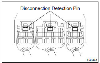
- Turn the ignition switch to lock.
- disconnect the negative (–) terminal cable from the battery, and wait at least for 90 seconds.
- with 3 connectors connected to the airbag sensor assy
center, place tester leads onto any 2 of 3 disconnection
detection pins and check for continuity.
Ok: continuity


Replace air bag sensor assy center


Other materials:
Audio unit
1 Bluetooth® connection status
If “BT” is not displayed, the Bluetooth® audio/phone cannot be used.
2 Display
A message, name, number, etc. is displayed.
Lower-case characters and special characters cannot be displayed.
3 Displays the set up menu
4 Selects items such as menu and number
...
Dialing from call history
You can make a call using the call history, which has the 3 functions below.
: calls which you missed
: calls which you received
: calls which you made
1 Display the phone screen.
2 Select “Call History” tab.
3 Select or the desired entry from
the list.
► When
is selected
4 C ...
Vehicle load limits
Vehicle load limits include total load capacity, seating capacity, towing
capacity and cargo capacity.
◆ Total load capacity (vehicle capacity weight):
Total load capacity means the combined weight of occupants, cargo and luggage.
◆ Seating capacity: 5 occupants (Front 2, Rear 3)
S ...