Toyota Corolla (E120) 2002–2008 Repair Manual / Diagnostics / Supplemental restraint system / Short in p/t squib (rh) circuit (to
ground) / Inspection procedure
Toyota Corolla (E120): Inspection procedure
1 Check p/t squib(rh) circuit(airbag sensor assy center – front seat outer belt assy rh)
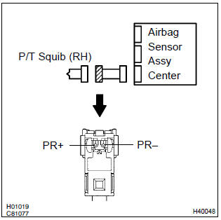
- Disconnect the negative (–) terminal cable from the battery, and wait at least for 90 seconds.
- disconnect the connectors between the airbag sensor assy center and the seat belt pretensioner (rh).
- for the connector (on the seat belt pretensioner side) between
the airbag sensor assy center and the seat belt pretensioner
(rh), measure the resistance between pr+
and body ground.
Ok: resistance: 1 mΩ or higher

2 Check air bag sensor assy center
Sst 09843–18040
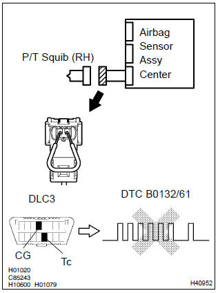
- Connect the connector to the airbag sensor assy center.
- using a service wire, connect pr+ and pr– of the connector (on the seat belt pretensioner side) between the airbag sensor assy center and the seat belt pretensioner (rh).
- connect the negative (–) terminal cable to the battery, and wait at least for 2 seconds.
- turn the ignition switch to on, and wait at least for 20 seconds.
- clear the dtc stored in memory .
- turn the ignition switch to lock, and wait at least for 20 seconds.
- turn the ignition switch to on, and wait at least for 20 seconds.
- check the dtc .
Ok: dtc b0132/61 is not output.
Hint
: codes other than code b0132/61 may be output at this time, but they are not relevant to this check.


3 Check p/t squib (rh)
Sst 09843–18040
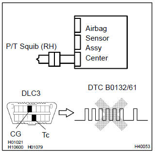
- Turn the ignition switch to lock.
- disconnect the negative (–) terminal cable from the battery, and wait at least for 90 seconds.
- connect the seat belt pretensioner (rh) connector.
- connect the negative (–) terminal cable to the battery, and wait at least for 2 seconds.
- turn the ignition switch to on, and wait at least for 20 seconds.
- clear the dtc stored in memory .
- turn the ignition switch to lock, and wait at least for 20 seconds.
- turn the ignition switch to on, and wait at least for 20 seconds.
- check the dtc .
Ok: dtc b0132/61 is not output.
Hint
: codes other than code b0132/61 may be output at this time, but they are not relevant to this check.


4 Use simulation method to check


Replace all srs components including the wire harness


Other materials:
Thermostat
Replacement
1. Remove engine under cover rh
2. Drain coolant
3. Remove fan and generator v belt
4. Remove generator assy
Disconnect the wire clamp from the wire clip on the rectifire
end frame.
remove the rubber cap and nut, and disconnect the alternator
wire.
d ...
Inspection procedure
1 Check p/t squib(lh) circuit(airbag sensor assy center – front seat
outer belt assy lh)
Disconnect the negative (–) terminal cable from the battery,
and wait at least for 90 seconds.
disconnect the connectors between the airbag sensor
assy center and the seat belt pretensio ...
Odometer and trip meter
display
■ Changing the display
Press the display change button
until the desired item is displayed.
■ Display items
Odometer
Displays the total distance the vehicle
has been driven.
Trip meter A/Trip meter B
Displays the distance the vehicle
has been driven since the meter
was last reset. Trip ...