Toyota Corolla (E120): Inspection
1. Charcoal canister assy
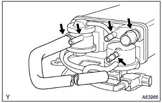
- Visually check the charcoal canister for cracks or damage.
- Inspect the charcoal canister operation.
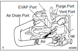
- Plug the vent port with the cap.
- While holding the purge port closed, blow air (1.76 Kpa, 18 gf/cm2, 0.26 Psi) into the evap port and check that air flows from the air drain port.
- While holding the purge port and the air drain port closed, blow air (1.76 Kpa, 18 gf/cm2, 0.26 Psi) into the evap port and check that air does not flow from the air inlet port.
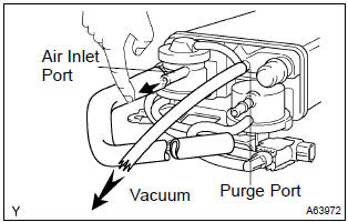
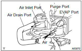
- Apply vaccum (3.43 Kpa, 25.7 Mmhg, 1.01 In.Hg) to the purge port, check that the vacuum dose not decrease when the air inlet port is closed, and check that the vacuum decreases when the air inlet port is released.
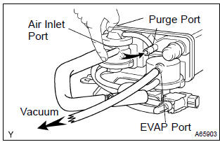
- While holding the air inlet port closed, apply vacuum
(3.43 Kpa, 25.7 Mmhg, 1.01 In.Hg) to the evap port
and check that air flows into the purge port.
If operation is not as spacified, replace the charcoal canister.
- Remove the hose and cap from vent port.
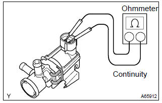
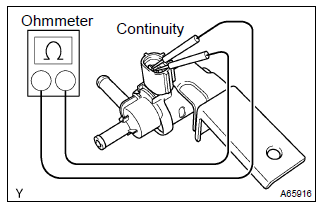
- Inspect vsv for pressure swiching valve
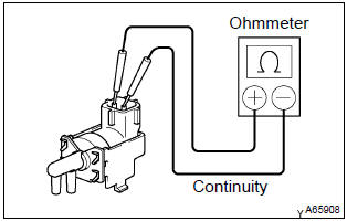
- using an ohmmeter, check that there is continuity
between the terminals.
Resistance: 37 – 44 w at 20 c (68 f) if there is no continuity, replace the vsv.
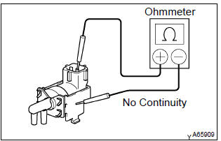
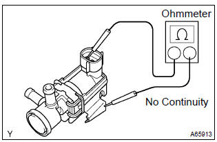
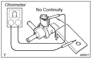
- Using an ohmmeter, check that there is no continuity
between each terminal and the body.
If there is continuity, replace the vsv.
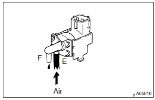
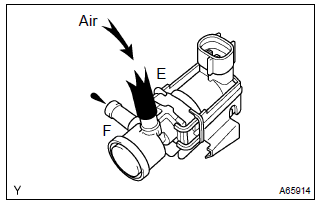
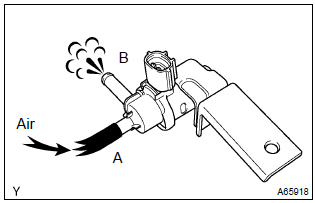
- Check that air does not flow from ports e to f.
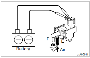
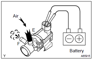
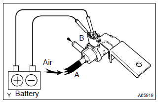
- Apply battery positive voltage across the terminals.
- Check that air flows from ports e to f.
If operation is not as specified, replace the vsv.
2. Ventilation valve sub–assy
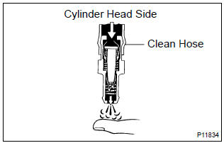
- Install clean hose to the pcv valve.
- inspect the pcv valve operation.
- Blow air into the cylinder head side, and check that air passes through easily.
Caution
: do not suck air through the valve. Petroleum substances inside the valve air harmful.
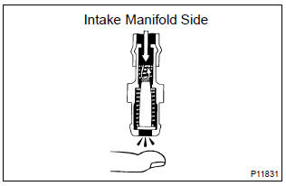
- Blow air into the intake manifold side, and check
that air passes through with difficulty.
If operation is not as specified, replace the pcv valve.
- remove clean hose from the pcv valve.
3. Fuel tank cap assy
- Visually check if cap and/or gasket are deformed or damaged.
If necessary, repair or replace the cap.
4. Vacuum switching valve no.1
- Inspect vsv for evaporative emission (evap).
- Using an ohmmeter, check that there is continuity
between the terminals.
Resistance: 27 – 33 Ω at 20 c (68 f) if there is no continuity, replace the vsv.
- Using an ohmmeter, check that there is no continuity
between each terminal and the body.
If there is continuity, replace the vsv.
- Check that air flows from ports e to f.
- Apply battery positive voltage across the terminals.
- Check that air does not flow from ports e to f.
If operation is not as specified, replace the vsv.
5. Vacuum switching valve assy no.1
- Inspect vsv for canister closed valve (ccv).
- Using an ohmmeter, check that there is continuity
between the terminals.
Resistance: 25 – 30 Ω at 20 c (68 f) if there is no continuity, replace the vsv.
- Using an ohmmeter, check that there is no continuity
between each terminal and the body.
If there is continuity, replace the vsv.
- Check that air flows from ports a to b.
- Apply battery positive voltage across the terminals.
- Check that air does not flow from ports a to b.
If operation is not as specified, replace the vsv.


Other materials:
Headlight aim (vehicles
with front side
marker lights [bulb
type] )
Vertical movement adjusting
bolts
Adjustment bolt A
Adjustment bolt B
Before checking the headlight
aim
Make sure the vehicle has a
full tank of gasoline and the
area around the headlight is
not deformed.
Park the vehicle on level
ground.
Make sure the tire inflation
pressure is at the ...
Overhaul
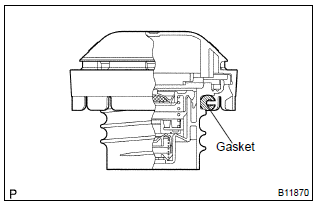
1. Remove w/head taper screw plug no.2
Using a socket hexagon wench 10, remove the taper
screw plug and gasket.
2. Remove valve lifter
Remove the valve lifters from the cylinder head.
3. Remove valve
Place the cylinder head on wooden blocks.
using sst, compres ...
Cruise control actuator assy
Replacement
1. Remove cruise control actuator cover
Disengage the 2 claws, then remove the cruise control actuator
cover.
2. Separate accelerator control cable assy
Loosen the double nut and separate the accelerator control
cable assy.
3. Separate accelerator auto drive ca ...