
Toyota Corolla (E120) 2002–2008 Repair Manual / Diagnostics / Toyota vehicle intrusion protection system / Ecu power source circuit
Toyota Corolla (E120): Ecu power source circuit
Circuit description
This circuit provides power to operate the tvip ecu.
Wiring diagram
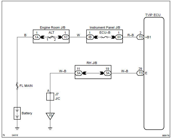
Inspection procedure
1 Check fuse (ecu–b)
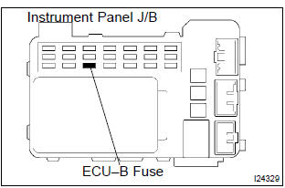
- Remove the fuse from the instrument panel j/b.
- check the continuity of the fuse.
Standard: continuity


2 Check tvip ecu
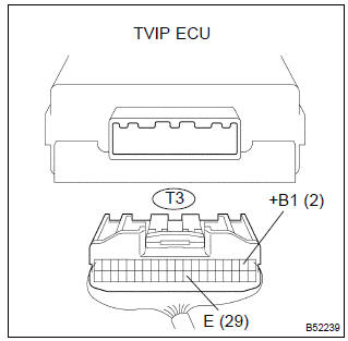
- Disconnect the tvip ecu connector.
- measure the voltage between the terminals of the ecu connector, as shown in the illustration and table.
Standard:



3 Check wire harness (tvip ecu body ground)
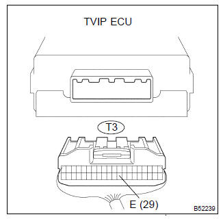
- Disconnect the tvip ecu connector.
- check the connector on the harness side, as shown in the illustration and table.
Standard:



Check and replace tvip ecu


Other materials:
Terminals of ecu
1. Inspect tvip ecu
Inspect the ecu–b, dome and ecu–ig fuses.
disconnect the tvip ecu connector, and the continuity and voltage of
check each terminal of the disconnected
connector.
Standard:
If the result is not as specified, the vehicle’s side may malfunction.
Reco ...
Body panel sealing areas
Be sure to apply body sealer to the body panel joints and door edges (tip of
outer panel folded part), etc., To waterproof
and rustproof them.
Hint:
apply degreasing agent to a clean cloth and clean the sealer
application areas.
After removing the applied spot sealer from the se ...
Inspection procedure
1 Check d squib circuit(airbag sensor assy center – horn button
assy)
Disconnect the negative (–) terminal cable from the battery,
and wait at least for 90 seconds.
disconnect the connector between the airbag sensor
assy center and the horn button assy.
for the black ...