Toyota Corolla (E120) 2002–2008 Repair Manual / Diagnostics / Supplemental restraint system / Tc terminal circuit / Circuit description
Toyota Corolla (E120): Circuit description
Dtc output mode is set by connecting between tc and cg of the dlc3.
The dtcs are displayed by blinking the srs warning light.
Wiring diagram
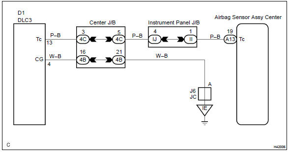
Hint
: when each warning light stays blinking, ground short in the wiring until the terminal tc of the dlc3 or internal ground short in each ecu is suspected.


Other materials:
Turning on the high beam headlights
1 With the headlights on, push the lever away from you to turn on the high beams.
Pull the lever toward you to the center position to turn the high beams off.
2 Pull the lever toward you and release it to flash the high beams once.
You can flash the high beams with the headlights on or off.
&# ...
Manual transmission / transaxle
Service data
Torque specification
...
If the vehicle battery is discharged
The following procedures may be used to start the engine if the vehicle’s
battery is discharged.
You can also call your Toyota dealer or a qualified repair shop.
If you have a set of jumper (or booster) cables and a second vehicle with a 12-volt
battery, you can jump start your vehicle by fo ...