Toyota Corolla (E120): Circuit description
The side squib (rh) circuit consists of the airbag sensor assy center and front seat airbag assy (rh).
It causes the srs to deploy when the srs deployment conditions are satisfied.
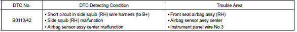
Dtc b0113/42 is recorded when a b+ short is detected in the side squib (rh) circuit.
Wiring diagram


Other materials:
Inspection procedure
1 Check operation(stop lamp swtich assy)
Check that the stop light comes on when the brake pedal is depressed,
and turns off when the brake
pedal is released.
2 Input signal check
See input signal check on page 05–745.
check the indicator light when the brake pedal ...
Seat heaters
Press the switch.
1 High temperature
2 Low temperature
The indicator light comes on when the switch is on.
■The seat heaters can be used when
► Vehicles without a smart key system
The engine switch is in the “ON” position.
►Vehicles with a smart key system
The engine ...
Outer rear view mirror assy lh
Replacement
Hint:
installation is according to the reverse order of the removal.
In the rh side, work in the same procedure as in the lh side.
1. Remove front armrest assy lh
2. Remove power window regulator master switch assy (w/ power window)
3. Remove front armrest base panel upper ...