Toyota Corolla (E120) 2002–2008 Repair Manual / Diagnostics / Sfi system / Vehicle speed sensor ”a” / Circuit description
Toyota Corolla (E120): Circuit description
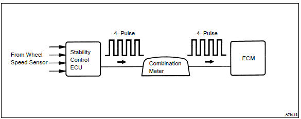
The vehicle equipped with abs detects a vehicle speed using the stability control ecu and wheel speed sensor. This sensor monitors a wheel rotation speed and sends the signal to the ecu.
The stability control ecu converts these wheel speed signals into a 4–pulse signal and outputs it to the ecm via the combination meter.
The ecm determines the vehicle speed based on the frequency of these pulse signals.
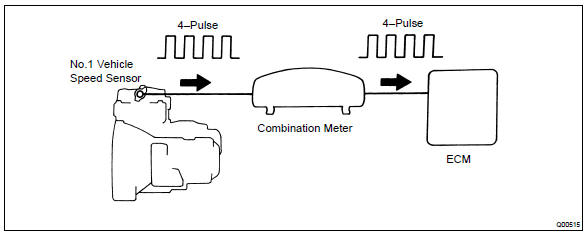
In the vehicle without abs, the no. 1 Vehicle speed sensor outputs a 4–pulse signal for every revolution of the rotor shaft, which is rotated by the transmission output shaft via the driven gear. After this signal is converted into a more precise rectangular waveform by the waveform shaping circuit inside the combination meter, it is then transmitted to the ecm. The ecm determines the vehicle speed based on the frequency of these pulse signal.
W/ abs:
W/o abs:
Monitor description
Equipped with abs:
the ecm assumes that the vehicle is driven when the rpm of the transmission counter gear indicates more than 300 rpm and it has been over 30 seconds since the park/neutral position switch was turned off. If there is no signal from the vehicle speed sensor with these conditions satisfied, the ecm concludes that there is a fault in the vehicle speed sensor. The ecm will turn on the mil and a dtc is set.
Not equipped with abs:
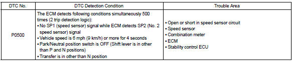
the ecm assumes that the vehicle is driven when the park/neutral position switch is off and it has been over 4 seconds since the actual vehicle speed was 9 km/h or more.
If there is no signal from the vehicle speed sensor with these conditions satisfied, the ecm concludes that there is a fault in the vehicle speed sensor. The ecm will turn on the mil and a dtc is set.
Monitor strategy
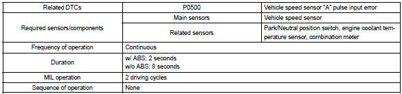
Typical enabling conditions
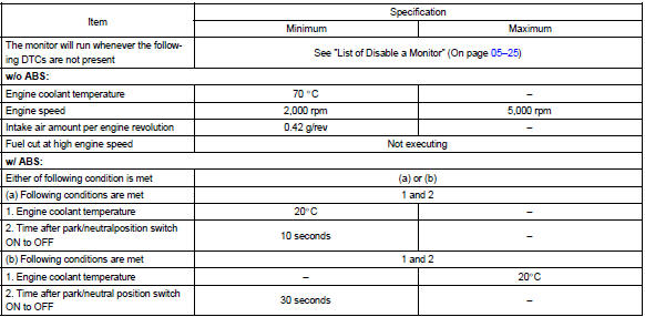
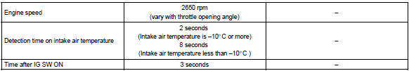
Typical malfunction thresholds

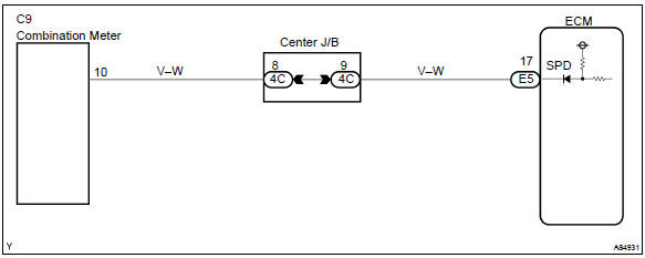
Wiring diagram


Other materials:
Content of driving information
■ Display items
Speedometer display/Driving
range
Fuel economy
Eco Driving Indicator/Driving
range
■ Speedometer display/Driving
range
Speedometer display
Driving range
Displays driving range with remaining
fuel. Use the displayed values
as a reference only.
This distance is computed ...
Manual transmission/transaxle
Preparation
Sst
Equipment
Lubricant
...
Speed control main switch assy
Replacement
1. Disconnect battery negative terminal
2. Inspect place front wheels facing straight ahead
3. Remove horn button assy
4. Remove steering wheel assy
sst 09950–50013 (09951–05010, 09952–05010, 09953–05020, 09954–05021)
5. Remove speed control main switch assy
Remov ...