Toyota Corolla (E120) 2002–2008 Repair Manual / Diagnostics / Sfi system / Ignition coil primary/secondary
circuit / Circuit description
Toyota Corolla (E120): Circuit description
Hint
:
- these dtcs indicate a malfunction related to the primary circuit.
- If dtc p0351 is displayed, check the no.1 Ignition coil with igniter circuit.
- If dtc p0352 is displayed, check the no.2 Ignition coil with igniter circuit.
- If dtc p0353 is displayed, check the no.3 Ignition coil with igniter circuit.
- If dtc p0354 is displayed, check the no.4 Ignition coil with igniter circuit.
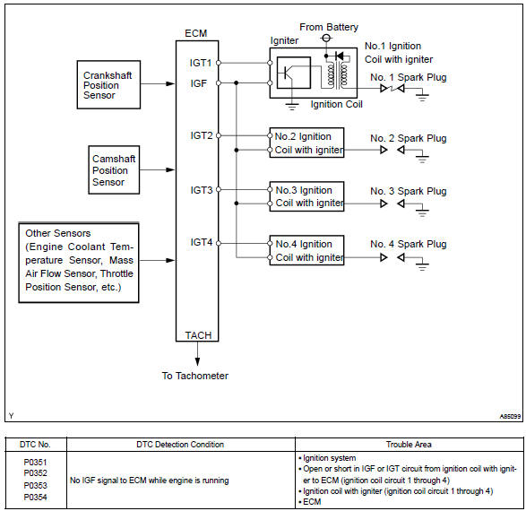
A direct ignition system (dis) is used on this vehicle. The dis improves the ignition timing accuracy, reduces high–voltage loss, and enhances the overall reliability of the ignition system by eliminating the distributor.
The dis is a 1–cylinder ignition system which ignites one cylinder with one ignition coil. In the 1–cylinder ignition system, the one spark plug is connected to the end of the secondary winding. High voltage generated in the secondary winding is applied directly to the spark plug. The spark of the spark plug passes from the center electrode to the ground electrode.
The ecm determines the ignition timing and outputs the ignition signals (igt) for each cylinder. Using the ignition (igt) signal, the ecm turns on and off the power transistor inside the igniter and this switches on and off the current to the primary coil. When the current flow to the primary coil is cut off, high–voltage is generated in the secondary coil and this voltage is applied to the spark plugs to spark inside the cylinders.
As the ecm cuts the current to the primary coil, the igniter sends back the ignition confirmation (igf) signal for each cylinder ignition to the ecm.
Monitor description
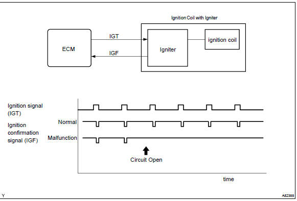
If the ecm does not receive the ignition confirmation signal (igf) after sending the ignition signal (igt), it interprets this as a fault in the igniter and sets a dtc.
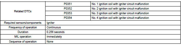
Monitor strategy
Typical enabling conditions
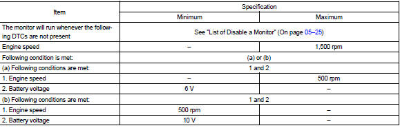
Typical malfunction thresholds

Component operating range

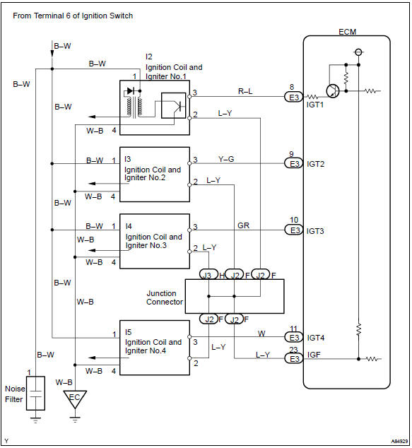
Wiring diagram


Other materials:
Antenna cord sub–assy
Replacement
Hint: components:
1. Remove instrument panel sub–assy upper
Hint:
refer to the procedure until the step, ”remove instrument panel sub–assy
upper” of
instrument panel sub–assy lower.
Remove the related parts as long as the antenna cord sub–assy can be
removed ...
Overhaul
Hint:
installation is in the reveres order of the removal. But the
installation is indicated only when it has a
point.
In the rh side, work in the same procedure as in the lh side.
1. Remove rear armrest assy lh
Using a screwdriver, remove the rear armrest.
Hint:
tape the s ...
On–vehicle inspection
1. Inspect front axle hub bearing
remove the front wheel.
separate the front disc brake caliper assy .
remove the front disc.
inspect the bearing backlash.
Using a dial indicator, check the backlash near the
center of the axle hub.
Maximum: 0.05 Mm (0. ...