Toyota Corolla (E120) 2002–2008 Repair Manual / Introduction / How to troubleshoot ecu controlled
systems / Symptom simulation
Toyota Corolla (E120): Symptom simulation
Hint
: the most difficult case in troubleshooting is when no symptoms occurs. In such cases, a thorough customer problem analysis must be carried out. Then the same or similar conditions and environment in which the problem occurred in the customer’s vehicle should be simulated. No matter how much experience a technician has, or how skilled he may be, if he proceeds to troubleshoot without confirming the problem symptoms, he will tend to overlook something important in the repair operation and make a wrong guess somewhere, which will only lead to a standstill. For example, for a problem which only occurs when the engine is cold, or for a problem which occurs due to vibration caused by the road during driving, etc., The problem can never be determined when the engine is hot or when the vehicles is at a standstill. Since vibration, heat or water penetration (moisture) is a likely cause for the problem which is difficult to reproduce, the symptom simulation tests introduced here are effective measures in a point that the external causes are applied to the vehicle in a stationary condition.
Important points in the symptom simulation test: in the symptom simulation test, the problem symptoms should be confirmed, and the problem area or parts must also be discovered. To do so, reduce the possible problem circuits according to the symptoms before starting this type of test and have the hand–held tester connected beforehand. After that, carry out the symptom simulation test, judging whether the circuit being tested is defective or normal and also confirming the problem symptoms at the same time. Refer to the problem symptoms table of each system to narrow down the possible causes of the symptom.
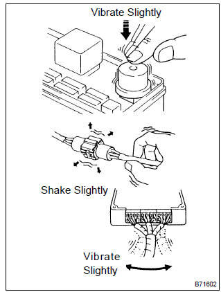
1. Vibration method: when vibration seems to be the major cause.
- Part and sensor
- apply slight vibration with your finger to the part of the sensor considered to be the problem cause and check whether the malfunction occurs.
Hint
: applying strong vibration to relays may result in open relays.
- Connectors
- slightly shake the connector vertically and horizontally.
- wire harness
- slightly shake the wire harness vertically and horizontally.
The connector joint and fulcrum of the vibration are the major areas that should be checked thoroughly.
2. Heat method: if the problem seems to occur when the area in question is heated.
- Heat the component that is the possible cause of the malfunction with a hair dryer or similar object. Check if the malfunction occurs.
Notice
:
- do not heat the components to more than 60 c (140 °F) (temperature is limited to keep the components from being damaged).
- Do not apply heat directly to the parts in the ecu.
3. Water sprinkling method: when the malfunction seems to occur on a rainy day or in high–humidity.
- Sprinkle water onto the vehicle and check if the malfunction occurs.
Notice
:
- never sprinkle water directly onto the engine compartment, but indirectly change the temperature and humidity by spraying a mist of water onto the radiator front surface.
- Never apply water directly onto the electronic components.
Hint
: if a vehicle is subject to water leakage, the leaking water may contaminate the ecu. When testing a vehicle with a water leakage problem, this factor must also be considered.
4. Others: if the malfunction seems to occur when electrical load is excessive.
- Turn on all the electrical equipment including the heater blower, headlights, rear window defogger, etc., And check if the malfunction occurs.


Other materials:
Circuit description
The ecm compares the two waveforms of the heated oxygen sensors located
before and after the catalyst
to determine whether or not the catalyst performance has deteriorated.
Air–fuel ratio feedback compensation keeps the waveform of the heated oxygen
sensor in front of the catalyst
alterna ...
Circuit description
The side squib (rh) circuit consists of the airbag sensor assy center and
front seat airbag assy (rh).
It causes the srs to deploy when the srs deployment conditions are satisfied.
Dtc b0110/43 is recorded when a short is detected in the side squib (rh)
circuit.
Wiring diagram
...
Turning on light switch does not light up night time
illumination of radio receiver
Wiring diagram
Inspection procedure
1 Inspect radio receiver assy(ill+, ill–)
Check that the voltage between terminals at each condition,
as shown in the chart.
Standard:
Repair or replace harness or connector ...