Toyota Corolla (E120) 2002–2008 Repair Manual / Diagnostics / Combination meter / Seat belt warning lamp for front passenger’s seat
does not flash
Toyota Corolla (E120): Seat belt warning lamp for front passenger’s seat does not flash
Wiring diagram
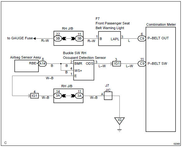
Inspection procedure
1 Inspect combination meter assy
- Ground terminal c9–11 on the combination meter side.
- check that the warning lightlights up.
Ok: warning light lights up.


2 Inspect passenger seat belt warning lamp assy
- Ground terminal c9–6 on the combination meter side.
- check that the warning lightlights up.
Ok: warning light lights up.

Check and replace combination meter assy
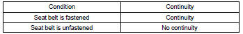
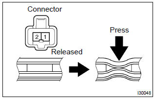
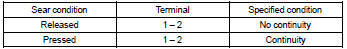
3 Inspect front seat inner belt assy rh
- Check continuity.
- Disconnect the front seat inner belt assy.
- Check the continuity in between terminals 1 and 2
of front seat inner belt assy rh.
Ok:

4 Inspect separate seat type front seat cushion pad
- Disconnect the separate type front seat cushion pad.
- check continuity separate type front seat cushion pad.

Repair or replace harness and connector


Other materials:
How to proceed with troubleshooting
The hand–held tester can be used at step 4, 6, 8 and 9.
1 Vehicle brought to workshop
2 Customer problem analysis
3 Warning light check
4 The dtcs check (present and past dtcs)
5 The dtcs chart
6 Circuit inspection
7 Repair
8 Clear the dtcs (present and past dtcs)
9 The dt ...
Emergency flashers
The emergency flashers are used to warn other drivers when the vehicle has
to be stopped in the road due to a breakdown, etc.
Press the switch.
All the turn signal lights will flash.
To turn them off, press the switch once again.
■Emergency flashers
If the emergency flashers are used ...
No sound is heard from speaker in all modes
Wiring diagram
Inspection procedure
1 Check lcd (liquid crystal display) for lighting
Lcd illumination check
turn the ignition switch acc.
Turn the radio receiver assembly on.
Standard: lcd illumination of the radio receiver assembly light.
2 Control fader and ...