Toyota Corolla (E120): Repair
1. Steering off center repair procedure
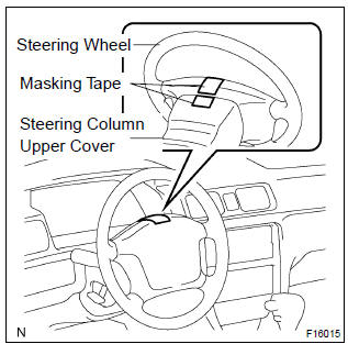
- Inspect steering wheel off center.
- Apply masking tape on the top center of the steering wheel and steering column upper cover.
- Driving the vehicle on a straight line for 100 meters at a constant speed of 35 mph (56 km/h), and hold the steering wheel to maintain the course.
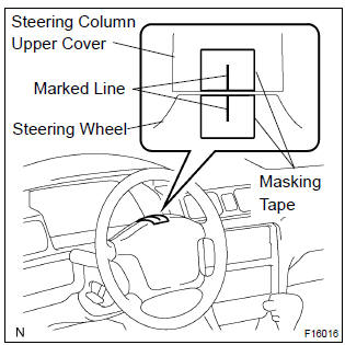
- Draw a line on the masking tape as shown in the illustration.
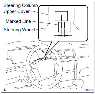
- Turn the steering wheel to its straight position.
Hint
: refer to the upper surface of the steering wheel, steering spoke and srs airbag line for the straight position.
- Draw a new line on the masking tape or the steering wheel as shown in the illustration.
- Measure the distance between the 2 lines on the masking tape of the steering wheel.
- Convert the measured distance to steering angle.
Measured distance 1 mm (0.04 In.) = Steering angle approximately 1 deg.
Hint
: make a note of the steering angle.
- adjust steering angle.
Notice
: the adjustment method for steering angle varies depending on the models. Check whether it is type a or b.
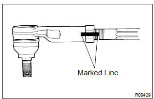
- Draw a line on the rh and lh tie rod and rack ends where it can easily be seen.
- Using a paper gauge, measure the distance from rh and lh tie rod ends to the rack end screws.
Hint
:
- measure the rh side and lh side.
- Make a note of the measured values.
- Remove the rh and lh boot clips from the rack boots.
- Loosen the rh and lh lock nuts.
- Turn the rh and lh rack end by the same amount
(but in different directions) according to the steering
angle.
1 Turn 360 deg. Of rack end (1.5 Mm (0.059 In.) Horizontal movement) – 12 deg. Of steering angle.
- Tighten the rh and lh lock nuts by the specified
torque.
Torque: 74 n·m (750 kgf·cm, 54 ft·lbf)
Notice
: make sure that the difference in length between rh and lh tie rod ends and rack end screws are within 1.5 Mm (0.059 In.).
- Install the rh and lh boot clips.


Other materials:
Other functions
■ Switching between outside air and recirculated air modes
Press .
The mode switches between outside air mode (indicator off) and recirculated air
mode (indicator on) each time is pressed.
■ Defogging the windshield
Defoggers are used to defog the windshield and front side w ...
Hood
Adjustment
Hint:
since the centering bolt is used as a hood hinge and hood lock
set bolt, the hood and hood lock can not be adjusted with it on.
Substitute a bolt with washer for the centering bolt.
1. Inspect hood sub–assy
Check that the clearance is within the standard value.
...
Warning buzzer does not sound (key reminder
warning, light reminder warning)
Wiring diagram
Inspection procedere
1 Check buzzer
Check that all of the warning buzzers sound.
2 Inspect front door courtesy lamp switch assy
3 Inspect un–lock warning switch assy
4 Check harness and connector(between un–lock warning switch
and combination meter as ...