Toyota Corolla (E120) 2002–2008 Repair Manual / Fuel / Fuel pump assy / Removal & installation and disassembly & reassembly
Toyota Corolla (E120): Removal & installation and disassembly & reassembly
1. Remove bench type rear seat cushion assy
2. Remove rear floor service hole cover
- Remove the rear service hole cover.
- Disconnect the fuel pump and vapor pressure sensor connector.
3. Work for preventing gasoline from spilling out
- Start the engine.
- after the engine has stopped on the its own, turn the ignition switch to lock.
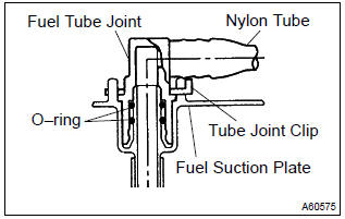
4. Disconnect fuel tank main tube sub–assy
- Remove the tube joint clip, and pull out the fuel tank main tube.
Notice
:
- check if there is any dirt like mud around the fuel tube joint before this work and clean dirt away.
- Be careful of dirt like mud because the fuel tube joint has an o–ring to seal the fuel tube joint and fuel suction plate.
- Do not use any tool in this work.
- Do not bend or twist the nylon tube by force.
- After disconnecting, cover the fuel tube joint with a vinyl bag.
- When the fuel tube joint and fuel suction plate are stuck, pinch the fuel tank main tube between fingers, and turn it carefully to free and then disconnect the fuel tank main tube.
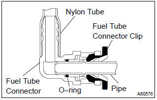
5. Disconnect fuel emission tube sub–assy no.1
- Pinch the fuel tube connector clip and then pull out the fuel emission tube.
Notice
:
- check if there is any dirt like mud around the fuel tube connector before this work and clean dirt away.
- Be careful of dirt like mud because the fuel tube connector has an o–ring to seal the fuel tube connector and pipe.
- Do not use any tool in this work.
- Do not bend or twist the nylon tube by force.
- After disconnecting, cover the fuel tube connector with a vinyl bag.
- When the fuel tube connector and pipe are stuck, pinch the fuel emission tube between fingers, and turn it carefully to free and then disconnect the fuel emission tube.
6. Remove fuel tank vent tube set plate
- Remove the 8 bolts and fuel tank vent tube set plate.
7. Remove fuel pump assembly
- Pull out the fuel pump assembly.
Notice
:
- do not damage the fuel pump filter.
- Be careful that the arm of the fuel sender gauge should not bent.
8. Remove fuel suction tube set gasket
- Remove the gasket from the fuel pump assembly.
9 Remove fuel suction tube set gasket
- Using a screwdriver, disconnect the 5 snap claws from the claw holes, and remove the fuel suction support.
Notice
: do not damage the fuel suction support.
10. Remove fuel pump cushion rubber
- Remove the fuel pump cushion rubber.
11. Remove fuel sender gage assy
- Disconnect the fuel sender gage connector.
- using a screwdriver, unlock the fuel sender gage, and slide it remove.
12. Remove fuel suction plate sub–assy
- Disconnect the fuel pump connector.
- using a screwdriver, disconnect the 4 snap claws from the claw holes, and remove the fuel suction plate.
Notice
: do not damage the fuel suction plate.
13. Remove vapor pressure sensor assy
- Remove the tube joint clip, and pull out the vapor pressure sensor.
14. Remove fuel pump harness
- Remove the fuel pump harness from the fuel suction plate.
15. Remove fuel pump
- Pull out the fuel pump from the fuel filter.
16. Remove fuel pump filter
- Using a small screwdriver, pry out the clip.
- pull out the fuel pump filter from the fuel pump.
17. Remove fuel pressure regulator assy
- Pull out the fuel pressure regulator from the fuel filter.
18. Remove fuel pressure regulator o–ring
- Remove an o–ring from the fuel pressure regulator.
19. Install fuel pressure regulator o–ring
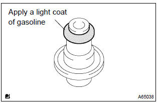
- Apply a light coat of gasoline to a new o–ring, and install it to the fuel pressure regulator.
20. Install fuel pump filter
- Install the fuel pump filter with a new clip.
21. Install fuel pump
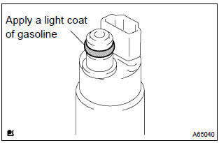
- Apply a light coat of gasoline to an o–ring, and install the fuel pump to the fuel filter.
22. Install vapor pressure sensor assy
- Install the vapor pressure sensor with the tube joint clip.
Notice
:
- check that there is no scratch or foreign objects on the connecting parts.
- Check that the fuel tube joint is inserted fully and securely.
- Check that the tube joint clip is on the collar of the fuel tube joint.
- After installing the tube joint clip, check that the fuel tube joint is not pulled off.
23. Install fuel suction tube set gasket
- install a new gasket to the fuel pump assembly.
24. Install fuel pump assembly
- install the fuel pump assembly to the fuel tank.
Notice
:
- do not damage the fuel pump filter.
- Be careful that the arm of the fuel sender gauge should not bent.
25. Install fuel tank vent tube set plate
- install the fuel tank vent tube set plate with the 8
bolts.
Torque: 6.0 Nvm (61 kgfvcm, 53 in.Vlbf)
26. Connect fuel emission tube sub–assy no.1
- push in the fuel emission tube to the pipe until fuel tube connector makes ”click” sound.
Notice
:
- check if there is any damage or foreign objects on the connected part.
- After connecting, check if the fuel tube connector and pipe are securely connected by pulling them.
27. Connect fuel tank main tube sub–assy
- connect the fuel tank main tube with the tube joint clip.
Notice
:
- check that there is no scratch or foreign objects on the connecting parts.
- Check that the fuel tube joint is inserted fully and securely.
- Check that the tube joint clip is on the collar of the fuel tube joint.
- After installing the tube joint clip, check that the fuel tube joint is not pulled off.
28. Check fuel leak
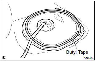
29. Install rear floor service hole cover
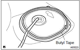
- Using the butyl tape, install the rear floor service hole cover.
30. Install bench type rear seat cushion assy


Other materials:
Body panel undercoating areas
Apply pastar uwe or pastar uc to the chassis, floor underside, sheet metal
fitting weld points of the body, and
inside of the wheel house to prevent rust and noise, as well as protect the body
from flying rocks.
Hint:
work must be performed while wearing the appropriate protective ...
Inspection
1. Intake air flow meter sub–assy
Inspect the intake air flow meter resistance.
Using an ohmmeter, measure the resistance between
terminals tha and e2.
Resistance:
at –20 c (–4 f) 13.6 To 18.4 KΩ
at 20 c (68 f) 2.21 To 2.69 KΩ
at 60 c (140 f) 0.49 To 0.67 ...
Inspection procedure
Hint:
read freeze frame data using the hand–held tester or the obd ii scan tool.
Freeze frame data records the
engine conditions when a malfunction is detected. When troubleshooting, it is
useful for determining whether
the vehicle was running or stopped, the engine was warmed up or not, th ...