Toyota Corolla (E120): Overhaul
1. Drain brake fluid
Notice
: wash the brake fluid off immediately if it comes into contact with any painted surface.
2. Remove air cleaner cap sub–assy
3. Remove brake master cylinder sub–assy
- disconnect the brake fluid level switch connector from master cylinder reservoir sub–assy.
- m/t: slide the clip and disconnect the clutch reservoir tube no.1 From master cylinder reservoir sub–assy.
- Using sst, disconnect the 2 brake tubes from the master
cylinder.
Sst 09023–00100

- Using sst, disconnect the 2 or 3 brake tubes from the
no.1 Way.
Sst 09023–00100
- Remove the 2 nuts, and pull out the master cylinder, no.1 Way and vacuum check valve bracket.
4. Remove brake master cylinder reservoir sub–assy
- remove the reservoir stopper screw and master cylinder reservoir sub–assy.
- remove the 2 cylinder reservoir grommets.
5. Remove brake master cylinder kit
- hold the master cylinder in the vise with the 2 aluminum plates in between.
- remove the o–ring.
- Push in the piston and remove the snap ring with snap ring pliers.
- Push in the piston and remove the piston stopper bolt and gasket.
- remove the no.1 Piston sub–assy by hand, pulling straight out not at an angle.
Notice
: if being pulled out at an angle, the piston may damage the cylinder bore.
- Place a cloth and 2 wooden blocks on the work table and lightly edges until the no.2 Piston sub–assy drops out of the cylinder.
Notice
: if being pulled out at an angle, the piston may damage the cylinder bore.
Hint
: make sure that the distance (a) from the cloth to the top of the blocks is at least 100 mm (3.94 In.).
6. Inspect brake master cylinder
- check the cylinder bore for rust or scoring.
7. Install brake master cylinder kit
- hold the master cylinder in the vise with the 2 aluminum plates in between.
- apply the lithium soap base glycol grease to the no.1 And no.2 Piston sub–assy.
- install the no.2 And no.1 Piston sub–assy to the master cylinder.
Notice
:
- if being inserted at an angle, the piston may damage the cylinder bore.
- Be careful not to damage the rubber lips on the pistons.
- Push in the piston and install a new gasket and a new piston
stopper bolt.
Torque: 10 nvm (102 Kgf·cm, 7 ft·lbf)
- Push in the piston and install the snap ring with snap ring pliers.
- apply the lithium soap base glycol grease to a new o– ring, and install the o–ring to the master cylinder.
8. Install brake master cylinder reservoir sub–assy
- apply the lithium soap base glycol grease to 2 brake master cylinder reservoir grommets.
- install the master cylinder reservoir with the screw.
Torque: 1.8 Nvm (18.4 Kgf·cm, 15.9 In.Vlbf)
9. Inspect and adjust brake booster push rod
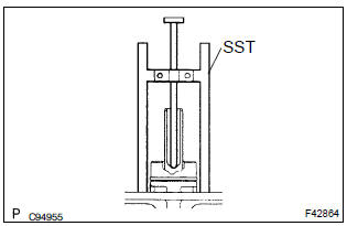
- Apply the chalk to the flat surfaced tip of the sst pin.
- set sst on the master cylinder and lower the pin of the
sst until it slightly touches the piston.
Sst 09737–00013
- Turn sst upside down and place it on the brake booster.
Sst 09737–00013 clearance: 0 mm (0 in.)
Hint
:
- if there is a space between the sst main body and the booster shell (chalk is applied to the booster push rod), it means that the clearance is too small.
- If chalk is not applied to the booster push rod after placing the sst on the brake booster, it means that the clearance is too large.
- If clearance is outside of the specified range, fix the push
rod using sst and adjust the length of the protruding adjusting
bolt.
Sst 09737–00020
Hint
: when adjusting the push rod, depress the brake pedal sufficiently so that the push rod sticks out.
10. Install brake master cylinder sub–assy
- install the master cylinder, no.1 Way and vacuum check
valve bracket with the 2 nuts.
Torque: 12.5 Nvm (127 Kgf·cm, 9 ft·lbf)
- Using sst, connect the 2 or 3 brake tubes to the no.1
Way.
Sst 09023–00100
torque: 15.2 Nvm (155 Kgf·cm, 11 ft·lbf)
- Using sst, connect the 2 brake tubes to the master cylinder.
Sst 09023–00100
torque: 15.2 Nvm (155 Kgf·cm, 11 ft·lbf) - m/t: connect the clutch reservoir tube no.1 With the clip to master cylinder reservoir sub–assy.
- connect the brake fluid level switch connector to master cylinder reservoir sub–assy.
11. Install air cleaner cap sub–assy
12. Fill reservoir with brake fluid
13. Bleed master cylinder
sst 09023–00100
14. Bleed brake line
15. Check fluid level in reservoir
16. Check brake fluid leakage


Other materials:
Connecting a Bluetooth® device
Up to 5 Bluetooth® devices (Phones (HFP) and audio players (AVP)) can be registered.
If more than 1 Bluetooth® device has been registered, select which device to
connect to.
1 Press the “SETUP” button.
2 Select “Bluetooth*”.
*: Bluetooth is a registered trademark of Bluetooth SIG, In ...
Circuit description
1 Check p squib circuit(airbag sensor assy center – instrument
panel passenger airbag assy)
Disconnect the negative (–) terminal cable from the battery,
and wait at least for 90 seconds.
disconnect the connectors between the airbag sensor
assy center and the instrument panel ...
If a warning light turns on or a
warning buzzer sounds
Calmly perform the following actions if any of the warning
lights comes on or flashes. If a light comes on or flashes, but
then goes off, this does not necessarily indicate a malfunction
in the system. However, if this continues to occur, have the
vehicle inspected by your Toyota dealer.
Actions to ...