Toyota Corolla (E120) 2002–2008 Repair Manual / Windshield/windowglass/mirror / Combination meter / On–vehicle inspection
Toyota Corolla (E120): On–vehicle inspection
1. Inspect speedometer
- check the operation.
- Using a speedometer tester, inspect the speedometer fro allowable indication error and check the operation of the odometer.
Reference:
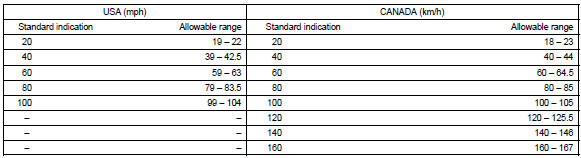
Notice
: tire wear and tire over or under inflation will increase the indication error.
- Check the deflection width of the speed meter indicator.
Reference: below 0.5 Km/h / 0.3 Mph
2. Inspect output signal of vehicle speed
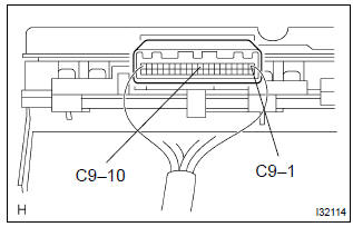
- Check for standard signal.
- While driving the vehicle at the speed of 10 km/h, check the voltage between the terminals c9–10 and c9–1 of the combination meter assy.
Standard: fluctuation between 10 to 14 v or less is repeated 7 times within 1 sec.
Notice
: check it with the ignition switch on and the connector connected.
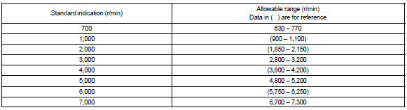
3. Inspect tachometer
- check the operation
- connect a tune–up test tachometer, and start the engine.
Notice
:
- reversing the connection of the tachometer will damage the transistors and diodes inside.
- When removing or installing the tachometer, be careful not to drop or subject it to heavy shocks.
- Compare the test and tachometer indications.
Dc 13.5 V, 25 c at (77 f)
4. Inspect fuel receiver gauge
- Inspect the circuit.
- Disconnect the connector from the sender gauge.
- Turn the ignition switch on, then check the position
of the receiver gauge needle.
Needle position: empty
- connect terminals 2 and 3 on the wire harness side
connector and turn the ignition switch on, then
check the position of the receiver gauge needle.
Needle position: full
5. Inspect fuel level warning
- inspect the circuit.
- Disconnect the connector from the sender gauge.
- Turn the ignition switch on, check the fuel level needle indicates empty and fuel level warning lights light on.
6. Inspect water temperature receiver gauge warning light
- inspect the circuit.
- Disconnect the connector from the sender gauge.
- Turn the ignition switch on, check the position of the water
temperature receiver gauge needle.
Needle position: cool
- connect between terminals on the wire harness side connector, then
check the position of the
water temperature receiver gauge needle.
Needle position: hot
7. Inspect low oil pressure warning ligh
t
- inspect the circuit.
- Disconnect the connector from the low oil pressure switch.
- Turn the ignition switch on.
- Connect the terminal of wire harness side connector and ground, then check the warning low oil pressure warning light.
Low oil pressure warning light: light on
8. Inspect low oil pressure switch
- check the continuity.
- Disconnect the connector from the low oil pressure switch.
- Check that continuity exists between terminal and ground.
Engine stopped: continuity engine running: no continuity
9. Inspect brake warning light
- inspect the parking brake warning light.
- Disconnect the connector from the parking brake switch and ground terminal on the wire harness side connector.
- Turn the ignition switch on and check that the warning light lights up.
- inspect the brake fluid level warning light.
- Disconnect the connector from the brake fluid level warning switch and connect terminals on the wire harness side connector.
- Turn the ignition switch on and check that the warning light lights up.
10. Inspect brake fluid level warning switch
- inspect the continuity.
- Remove the reservoir tank cap and strainer.
- Disconnect the connector.
- Check that the continuity exists between the terminals.
Float up (switch off): no continuity
- use syphon, etc., To take fluid out of the reservoir tank.
- Check that the continuity exists between the terminals.
Float down (switch on): continuity
- pour the fluid back in the reservoir tank.
11. Inspect light auto turn off buzzer
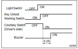
- Check the operation.
Hint
: when the key unlock warning and light auto turn off warning is output simultaneously, the key unlock warning precedes the other.
- Remove the ignition key with the tail light switch on
and the driver side door open and check for the
buzzer.
Buzzer sound: continuous
- while the buzzer is sounding, perform any of the following and check that the buzzer sound is stopped.
- Turn the tail light switch off.
- Close the driver side door.
- Insert the ignition key into the key cylinder.
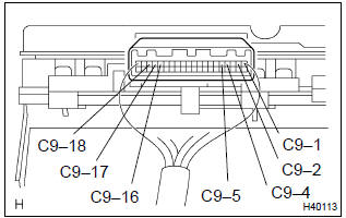
- Check the function.
- Remove the combination meter.
- Connect the position (+) lead from battery to terminal c9–5 and negative (–) lead to terminal c9–1 and c9–2.
- Connect the position (+) lead from battery to terminal
c9–18 and negative (–) lead to terminal c9–16
and c9–17, check that the buzzer sound.
Buzzer sound: continuous
- while the buzzer is sounding, connect the battery positive terminal to terminal c9–4 and check that the buzzer sound is stopped.
12. Inspect key unlock warning buzzer
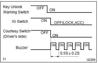
- Check the operation.
Hint
: when the key unlock warning and light auto turn off warning is output simultaneously, the key unlock warning precedes the other.
- While the driver side door is open, insert the ignition key, set the ignition switch to off (lock or acc) and check for the buzzer sound.
Buzzer sound: intermittent
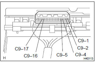
- Check the function.
- Remove the combination meter.
- Connect the position (+) lead from battery to terminal c9–5 and negative (–) lead to terminal c9–1 and c9–2.
- Connect the negative (–) lead to terminal c9–16
and c9–17, check that the buzzer sound.
Buzzer sound: intermittent
- While the buzzer is sounding, connect the battery positive terminal to terminal c9–4 and check that the buzzer sound is stopped.


Other materials:
On–vehicle inspection
Notice:
”cold” and ”hot” in these sentences express the temperature of the coils
themselves. ”Cold” is from
–10 c (14 f) to 50 c (122 f) and ”hot” is from 50 c (122 f) to 100 c (212 f).
1. Inspect ignition coil (with igniter) and spark test
confirm dtc.
Notice:
...
Receiving a phone call
Answering the phone
Press the off-hook switch.
Refusing a call
Press the on-hook switch.
Receiving a call when on another call
Press the off-hook switch.
Pressing the off-hook switch again returns you to the previous call.
Adjusting the ringtone volume when receiving a call
Change the ringto ...
Bluetooth® Audio (Multimedia system)
Listening to Bluetooth® Audio
The Bluetooth® audio system enables the user to enjoy music played on a portable
player from the vehicle speakers via wireless communication.
When a Bluetooth® device cannot be connected, check the connection status on
the “Bluetooth* Audio” screen. If the ...