Toyota Corolla (E120) 2002–2008 Repair Manual / Emission control / Emission control system / On–vehicle inspection
Toyota Corolla (E120): On–vehicle inspection
1. Inspect air–fuel ratio compensation system
Hint
: you can also check the system by choosing ”data monitor”, then ”o2 sensor output voltage” on the monitor of the hand–held tester.
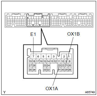
- Connect the hand–held tester to the terminal 23 (ox1a)
@ 7 (e1) and 21 (ox1b) @ 7 (e1) of the ecm.
Caution
: connect test leads from the back side of the connector with the ecu connected.
- warm up the oxygen sensor with the engine speed at 2,500 rpm for approx. 2 Minutes.
- confirm that the voltage changes between 0v to 1v with
the engine speed at 2,500 rpm.
Ok: the voltage changes more than 8 times in 10 seconds.
Caution
:
- perform the check immediately after the end of the warming up.
- If not confirming the change of voltage, warming up the oxygen sensor again.
2. Inspect fuel cut off rpm
- Increase the engine speed to at least 3,500 rpm.
- use a sound scope to check for injector operating noise.
- check that when the throttle lever is released, injector operation noise stops momentarily and then resumes.
3. Inspect evaporative emission control system
- After starting the engine, disconnect the vacuum hose shown in the illustration.
- confirm vacuum occurs at the vsv port, when choosing ”active test” and ”purge vsv” according to the display on hand–held tester.
- finish ”active test”, then connect the vacuum hose again.
- after going to ”ecm data monitor” on the hand–held tester, choose ”purge vsv” to check the operation of the purge vsv.
- after warm up the engine and drive the vehicle, confirm the vsv turns on from off.
4. Inspect evap system line
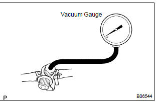
- Warm up the engine and stop the engine. Allow the engine to warm up to normal operating temperature.
- install a vacuum gauge (evap control system test equipment vacuum gauge) to the evap service port on the purge line.
- Toyota hand–held tester: forced driving of the vsv for the evap.
- Connect a toyota hand–held tester to the dlc3
- start the engine.
- Push the toyota hand–held tester main switch on.
- Use the active test mode on the toyota hand–held tester to operate the vsv for the evap.
- If you have no toyota hand–held tester: forced driving of the vsv for the evap.
- Disconnect the vsv connector for the evap.
- Connect the positive (+) and negative (–) leads from the battery to the vsv terminals for the evap.
- Start the engine.
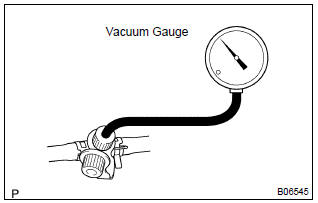
- Check the vacuum at idle vacuum: maintain at 0.368 – 19.713 In.Hg (5 –268 in.Aq) for over 5 seconds.
Hint
: if the vacuum does not change, you can conclude that the hose connecting the vsv to the service port has come loose or is blocked, or the vsv is malfunctioning.
- Toyota hand–held tester: conclude forced driving of the vsv for the evap.
- Stop the engine.
- Disconnect the toyota hand–held tester from the dlc3.
- if you have no toyota hand–held tester: conclude forced driving of the vsv for the evap.
- Stop the engine.
- Disconnect the positive (+) and negative (–) leads from the battery from the vsv terminals for the evap.
- Connect the vsv connector for the evap.
- disconnect the vacuum gauge from the evap service port on the purge line.
- connect a pressure gauge to the evap service port on the purge line.
- Check the pressure.
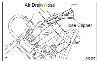
- Close off the air drain hose at the marked position of the canister with a hose clipper or similar instrument.
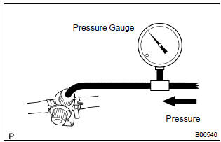
- Add the pressure (13.5 – 15.5 In. Aq) from the evap
service port.
Pressure:
2 minutes after the pressure is added, the gauge should be over 7.7–8.8 In.Aq.
Hint
: if you can not add pressure, you can conclude that the hose connecting the vsv – canister – fuel tank has slipped off or the vsv is open.
- Check if the pressure decreases when the fuel tank cap is removed while adding pressure.
Hint
: if the pressure dose not decrease when the filler cap is removed, then you can conclude that the hose connecting the service port to the fuel tank is blocked, etc.
- disconnect the pressure gauge from the evap service port on the purge line.
5. Check airtightness in fuel tank and filler pipe
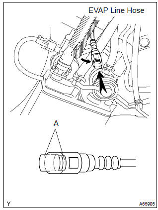
- Disconnect the evap line hose from the charcoal canister.
- Pinch portion a.
- Pull out the connector.
- pressurize and make the internal pressure in the fuel tank 4 kpa (41 gf/cm2, 0.58 Psi).
- check that the internal pressure of the fuel tank can be hold for 1 minute.
- check the connected portions of each hose and pipe.
- check the installed parts on the fuel tank.
If there is no abnormality, replace the fuel tank and filler pipe.
- reconnect the evap line hose to the charcoal canister.
6. Inspect fuel cut off valve and fill check valve
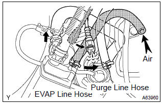
- Disconnect the purge line hose and evap line hose from the charcoal canister.
- plug the cap to the air drain hose.
- pressurize 4 kpa (41 gf/cm2, 0.58 Psi) to the purge port
and check that there is ventilation through the evap line
hose.
Hint
: in the condition that the fuel is full, as the float value of the fill check valve is closed and has no ventilation, it is necessary to check the fuel amount (volume).
- check if there is anything struck in the vent line hose and
evap line hose.
If there is no stuck in hoses, replace the fuel cut off valve and fill check valve.
- reconnect the purge line hose and evap line hose to the charcoal canister.
7. Check air inlet line
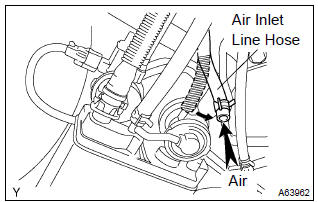
- Disconnect the air inlet line hose from the charcoal canister.
- check that there is ventilation in the air inlet line.
- reconnect the air inlet line hose to the charcoal canister.
8. Visually inspect hoses, connections and gaskets
- Check for cracks, leaks or damage.
Hint
: separation of the engine oil dipstick, oil filler cap, pcv hose, etc. May cause the engine to run out of turn. Disconnection, looseness or cracks in the parts of the air induction system between the throttle body and cylinder head will allow air suction and cause the engine to run out of turn.
9. Inspect heater resistance of heated oxygen sensor
- Disconnect the oxygen sensor connector.
- using an ohmmeter, measure the resistance between the
terminals ht and +b.
Resistance: 11 – 16 w at 20 c (68 f)
10. Inspect fuel tank cap
- Visually check if the cap and/or gasket are deformed or damaged.


Other materials:
Circuit description
A thermistor is built in the engine coolant temperature sensor and changes
the resistance value according
to the engine coolant temperature.
The structure of the sensor and connection to the ecm is the same as those of
the intake air temperature
sensor.
Hint:
if the ecm detects the dtc ...
Driving assist systems
To help enhance driving safety and performance, the following systems operate
automatically in response to various driving situations. Be aware, however, that
these systems are supplementary and should not be relied upon too heavily when operating
the vehicle.
◆ ABS (Anti-lock Brake Sys ...
Sliding roof/convertible
Service data
Torque specification
Engine hood/door
Torque specification
Exterior/interior trim
Torque specification
Cruise control
Service data
Torque specification
...