Toyota Corolla (E120) 2002–2008 Repair Manual / Diagnostics / Supplemental restraint system / Short in p squib (2nd step) circuit / Inspection procedure
Toyota Corolla (E120): Inspection procedure
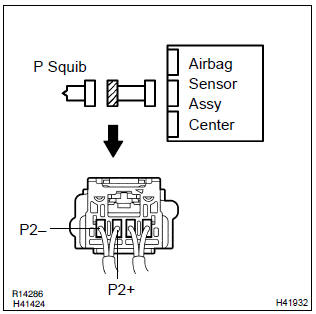
1 Check p squib circuit(airbag sensor assy center – instrument panel passenger airbag assy)
- Disconnect the negative (–) terminal cable from the battery, and wait at least for 90 seconds.
- disconnect the connectors between the airbag sensor assy center and the instrument panel passenger airbag assy.
- release the airbag activation prevention mechanism of the connector (on the airbag sensor assy center side) between the airbag sensor assy center and the instrument panel passenger airbag assy .
- for the connector (on the instrument panel passenger airbag
assy side) between the airbag sensor assy center
and the instrument panel passenger airbag assy, measure
the resistance between p2+ and p2–.
Ok: resistance: 1 mw or higher

2 Check air bag sensor assy center
Sst 09843–18040
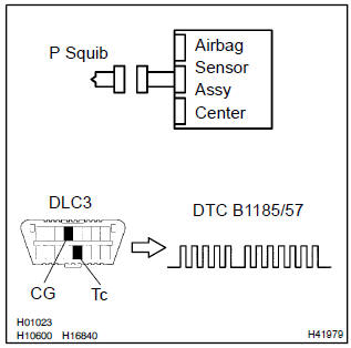
- Connect the connector to the airbag sensor assy center.
- connect the negative (–) terminal cable to the battery, and wait at least for 2 seconds.
- turn the ignition switch to on, and wait at least for 20 seconds.
- clear the dtc stored in memory .
- turn the ignition switch to lock, and wait at least for 20 seconds.
- turn the ignition switch to on, and wait at least for 20 seconds.
- check the dtc .
Ok: dtc b1185/57 is not output.
Hint
: codes other than code b1185/57 may be output at this time, but they are not relevant to this check.


3 Check p squib
Sst 09843–18040
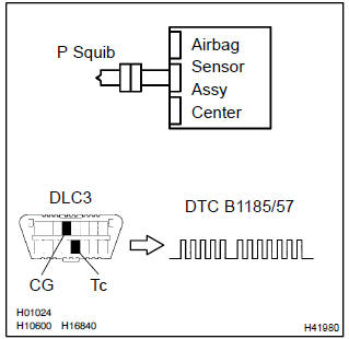
- Turn the ignition switch to lock.
- disconnect the negative (–) terminal cable from the battery, and wait at least for 90 seconds.
- connect the instrument panel passenger airbag assy connector.
- connect the negative (–) terminal cable to the battery, and wait at least for 2 seconds.
- turn the ignition switch to on, and wait at least for 20 seconds.
- clear the dtc stored in memory .
- turn the ignition switch to lock, and wait at least for 20 seconds.
- turn the ignition switch to on, and wait at least for 20 seconds.
- check the dtc .
Ok: dtc b1185/57 is not output.
Hint
: codes other than code b1185/57 may be output at this time, but they are not relevant to this check.

Use simulation method to check


Other materials:
Inspection procedure
Hint:
hand–held tester only:
narrowing down the trouble area is possible by performing ”a/f control” active
test (heated oxygen
sensor or other trouble areas can be distinguished).
Perform active test using hand–held tester (a/f control).
Hint:
”a/f control” is the active te ...
How to proceed with troubleshooting
Hint:
troubleshooting of the wireless door lock control system is based on
the premise that the power door
lock system is operating normally. Therefore, before troubleshooting the
wireless door lock control system,
first make certain that the the power door lock system is operating
...
Sound quality is bad only when playing tape
Inspection procedure
1 Replace cassette tape with another and recheck
Replace the cassette tape with another and recheck.
Replace the faulty cassette tape with the normal one to see if the
same trouble occurs again.
Standard: malfunction disappear.
2 Check for any foreig ...