Toyota Corolla (E120) 2002–2008 Repair Manual / Diagnostics / Supplemental restraint system / Side airbag sensor assy (rh)
malfunction / Inspection procedure
Toyota Corolla (E120): Inspection procedure
1 Check side air bag sensor assy rh
Sst 09843–18040
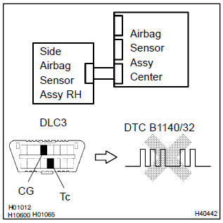
- Connect the negative (–) terminal cable to the battery, and wait at least for 2 seconds.
- turn the ignition switch to on, and wait at least for 20 seconds.
- clear the dtc stored in memory .
- turn the ignition switch to lock, and wait at least for 20 seconds.
- turn the ignition switch to on, and wait at least for 20 seconds.
- check the dtc .
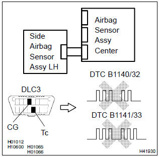
Ok: dtc b1140/32 is not output.
Hint
: codes other than code b1140/32 may be output at this time, but they are not relevant to this check.


2 Check airbag sensor assy center connector
- Turn the ignition switch to lock.
- disconnect the negative (–) terminal cable from the battery, and wait at least for 90 seconds.
- check that the connectors is properly connected to the airbag sensor assy center.


3 Check side airbag sensor assy connector
- Check that the connector is properly connected to the side airbag sensor assy (rh).


4 Check side airbag sensor assy(rh) circuit(open)(airbag sensor assy center – side airbag sensor assy rh)
Sst 09843–18040
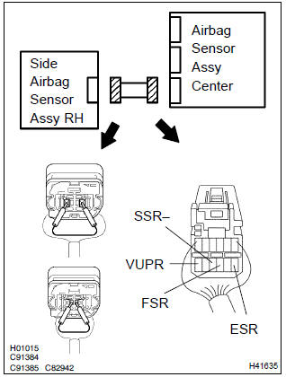
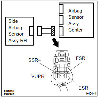
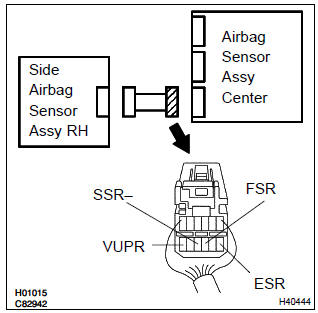
- Disconnect the connectors between the airbag sensor assy center and the side airbag sensor assy rh.
- using a service wire, connect vupr and esr, and fsr and ssr– of the connector (on the side airbag sensor assy side) between the airbag sensor assy center and the side airbag sensor assy (rh).
- for the connector (on the airbag sensor assy center side)
between the side airbag sensor assy rh and the airbag
sensor assy center, measure the resistance between
vupr and esr, and between fsr and ssr–.
Ok: resistance: below 1 Ω

5 Check side airbag sensor assy(rh) circuit(to ground)(airbag sensor assy center – side airbag sensor assy rh)
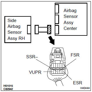
- Disconnect the connection between vupr and esr, and between fsr and ssr–.
- for the connector (on the airbag sensor assy center side)
between the airbag sensor assy center and the side airbag
sensor assy (rh), measure the resistance between
each terminal of vupr, ssr– and fsr, and body
ground.
Ok: resistance: 1mΩ or higher

6 Check side airbag sensor assy(rh) circuit(airbag sensor assy center – side airbag sensor assy rh)
- For the connector (on the airbag sensor assy center side)
between the airbag sensor assy center and the side airbag
sensor assy (rh), measure the resistance between
vupr and esr, and between fsr and ssr–.
Ok: resistance: 1mΩ or higher

7 Check side airbag sensor assy(rh) circuit(to b+)(airbag sensor assy center – aide airbag sensor assy rh)
- Connect the negative (–) terminal cable to the battery, and wait at least for 2 seconds.
- turn the ignition switch to on.
- for the connector (on the airbag sensor assy center side)
between the airbag sensor assy center and the side airbag
sensor assy (rh), measure the voltage between
each terminal of vupr, ssr– and fsr, and body
ground.
Ok: voltage: below 1 v

8 Check side air bag sensor assy rh
Sst 09843–18040
- Turn the ignition switch to lock.
- disconnect the negative (–) terminal cable from the battery, and wait at least for 90 seconds.
- connect the airbag sensor assy center connector.
- interchange the side airbag sensor assy (rh) and lh and connect the connectors to them.
- connect the negative (–) terminal cable to the battery, and wait at least for 2 seconds
- turn the ignition switch to on, and wait at least for 20 seconds.
- clear the dtc stored in memory .
- turn the ignition switch to lock, and wait at least for 20 seconds.
- turn the ignition switch to on, and wait at least for 20 seconds.
- check the dtc .
Ok: (a): dtc b1140/32 is not output.
(B): dtc b1141/33 is not output.

9 Use simulation method to check


Replace all srs components including the wire harness


Other materials:
Inspection procedure
1 Check relay (marking: starter cut)
Inspect the relay continuity, as shown in the illustration
and table.
Standard:
2 Check tvip ecu
Disconnect the tvip ecu connector.
turn the ignition switch position to the start.
measure the voltage between the termina ...
Drive shaft / propeller shaft
Preparation
Sst
Recomended tools
Equipment
Lubricant
...
Replacement
Hint: components:
1. Remove front wheel
2. Remove front axle hub lh nut
sst 09930–00010
3. Separate front stabilizer link assy lh
4. Separate speed sensor front lh (w/ abs)
5. Separate front disc brake caliper assy lh
Remove the 2 bolts, separate the brake caliper assy ...