Toyota Corolla (E120) 2002–2008 Repair Manual / Diagnostics / Supplemental restraint system / Short in p squib circuit (to ground) / Inspection procedure
Toyota Corolla (E120): Inspection procedure
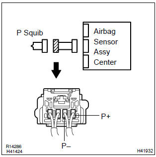
1 Check p squib circuit(airbag sensor assy center – instrument panel passenger airbag assy)
- Disconnect the negative (–) terminal cable from the battery, and wait at least for 90 seconds.
- disconnect the connectors between the airbag sensor assy center and the instrument panel passenger airbag assy.
- for the connector (on the instrument panel passenger airbag
assy side) between the airbag sensor assy center
and the instrument panel passenger airbag assy, measure
the resistance between p+ and body ground.
Ok: resistance: 1 mΩ or higher

2 Check air bag sensor assy center
Sst 09843–18040
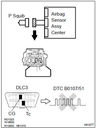
- Connect the connector to the airbag sensor assy center.
- using a service wire, connect p+ and p– of the connector (on the instrument panel passenger airbag assy side) between the airbag sensor assy center and the instrument panel passenger airbag assy.
- connect the negative (–) terminal cable to the battery, and wait at least for 2 seconds.
- turn the ignition switch to on, and wait at least for 20 seconds.
- clear the dtc stored in memory .
- turn the ignition switch to lock, and wait at least for 20 seconds.
- turn the ignition switch to on, and wait at least for 20 seconds.
- check the dtc .
Ok: dtc b0107/51 is not output.
Hint
: codes other than code b0107/51 may be output at this time, but they are not relevant to this check.


3 Check p squib
Sst 09843–18040
- Turn the ignition switch to lock.
- disconnect the negative (–) terminal cable from the battery, and wait at least for 90 seconds.
- connect the instrument panel passenger airbag assy connector.
- connect the negative (–) terminal cable to the battery, and wait at least for 2 seconds.
- turn the ignition switch to on, and wait at least for 20 seconds.
- clear the dtc stored in memory .
- turn the ignition switch to lock, and wait at least for 20 seconds.
- turn the ignition switch to on, and wait at least for 20 seconds.
- check the dtc .
Ok: dtc b0107/51 is not output.
Hint: codes other than code b0107/51 may be output at this time, but they are not relevant to this check.

4 Use simulation method to check


Replace all srs components including the wire harness


Other materials:
Stopping
► Automatic transmission or continuously
variable transmission
1 With the shift lever in D, depress the brake pedal.
2 If necessary, set the parking brake.
If the vehicle is to be stopped for an extended period of time, shift the shift
lever to P or N. (, 174, 176) ► Manual ...
Inspection procedure
1 Inspect dlc3 terminal voltage(tc terminal)
Turn the ignition switch to on.
measure voltage between terminals tc and cg of dlc3.
Ok:
voltage: 10 – 14 v
2 Check harness and connector(dlc3 – body ground)
Check for open and short circuit in harness and connector betw ...
Inspection procedure
Hint:
start the inspection from step 1 in case of using the hand–held tester and start
from step 2 in case of not
using the hand–held tester.
1 Read value of hand–held tester(front speed sensor)
Select the datalist mode on the hand–held tester.
check that there is no differe ...