Toyota Corolla (E120) 2002–2008 Repair Manual / Diagnostics / Supplemental restraint system / Short in d squib circuit (to b+) / Inspection procedure
Toyota Corolla (E120): Inspection procedure
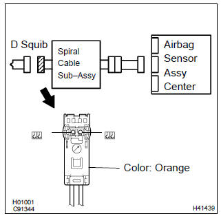
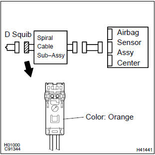
1 Check d squib circuit(airbag sensor assy center – horn button assy)
- Disconnect the negative (–) terminal cable from the battery, and wait at least for 90 seconds.
- disconnect the connectors between the airbag sensor assy center and the horn button assy.
- connect the negative (–) terminal cable to the battery, and wait at least for 2 seconds.
- turn the ignition switch to on.
- for the orange connector (on the spiral cable sub–assy
side) between the horn button assy and the spiral cable
sub–assy, measure the voltage between d+ and body
ground.
Ok: voltage: below 1 v


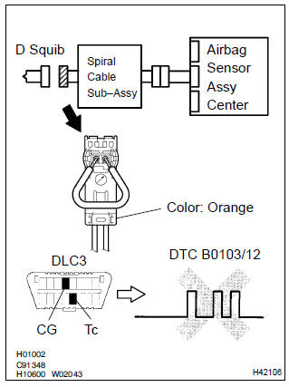
2 Check air bag sensor assy center
- Turn the ignition switch to lock.
- disconnect the negative (–) terminal cable from the battery, and wait at least for 90 seconds.
- connect the connector to the airbag sensor assy center.
- using a service wire, connect d+ and d– of the orange connector (on the spiral cable sub–assy side) between the horn button assy and the spiral cable sub–assy.
- connect the negative (–) terminal cable to the battery, and wait at least for 2 seconds.
- turn the ignition switch to on, and wait at least for 20 seconds.
- clear the dtc stored in memory .
- turn the ignition switch to lock, and wait at least for 20 seconds.
- turn the ignition switch to on, and wait at least for 60 seconds.
- check the dtc .
Ok: dtc b0103/12 is not output.
Hint
: codes other than code b0103/12 may be output at this time, but they are not relevant to this check.


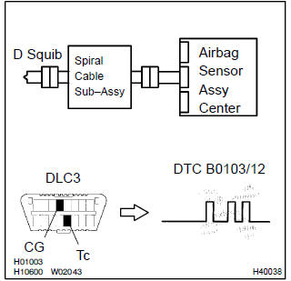
3 Check d squib
Sst 09843–18040
- Turn the ignition switch to lock.
- disconnect the negative (–) terminal cable from the battery, and wait at least for 90 seconds.
- connect the horn button assy connectors.
- connect the negative (–) terminal cable to the battery, and wait at least for 2 seconds.
- turn the ignition switch to on, and wait at least for 20 seconds.
- clear the dtc stored in memory .
- turn the ignition switch to lock, and wait at least for 20 seconds.
- turn the ignition switch to on, and wait at least for 20 seconds.
- check the dtc .
Ok: dtc b0103/12 is not output.
Hint
: codes other than code b0103/12 may be output at this time, but they are not relevant to this check.


4 Use simulation method to check


Replace all srs components including the wire harness
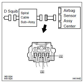
5 Check instrument panel wire(airbag sensor assy center – spiral cable sub–assy)
- Turn the ignition switch to lock.
- disconnect the connectors of the instrument panel wire.
- turn the ignition switch to on.
- for the connector (on the spiral cable sub–assy side) between
the airbag sensor assy center and the spiral cable
sub–assy, measure the voltage between d+ and body
ground.
Ok: voltage: below 1 v

6 Check spiral cable sub–assy
- For the orange connector (on the spiral cable sub–assy
side) between the horn button assy and the spiral cable
sub–assy, measure the voltage between d+ and body
ground.
Ok: voltage: below 1 v

7 Use simulation method to check


Replace all srs components including the wire harness


Other materials:
If you have a flat tire
Your vehicle is equipped
with a spare tire. The flat tire
can be replaced with the
spare tire.
WARNING
■If you have a flat tire
Do not continue driving with a flat
tire. Driving even a short distance
with a flat tire can damage the tire
and the wheel beyond repair,
which could result in an acciden ...
Symptom simulation
Hint:
the most difficult case in troubleshooting is when no symptoms occurs. In such
cases, a thorough customer
problem analysis must be carried out. Then the same or similar conditions and
environment in which the
problem occurred in the customer’s vehicle should be simulated. No matter ho ...
Data list/active test
1. Data list
Hint:
using the data list displayed by the hand–held tester or the obd ii scan tool,
you can read the value of
the switches, sensors, actuators and so on without parts removal. Reading the
data list as a first step
of troubleshooting is one method to shorten diagnostic time.
...