
Toyota Corolla (E170) 2014–2019 Owners Manual / Operation of each component / Adjusting the seats / Inside rear view mirror / Anti-glare function
Toyota Corolla (E170): Anti-glare function
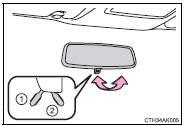
► Manual anti-glare inside rear view mirror
Reflected light from the headlights of vehicles behind can be reduced by operating the lever.
1 Normal position
2 Anti-glare position
► Auto anti-glare inside rear view mirror
Responding to the level of brightness of the headlights of vehicles behind, the reflected light is automatically reduced.
Changing automatic anti-glare function mode
On/off
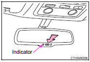
When the automatic anti-glare function is in ON mode, the indicator illuminates.
Vehicles without a smart key system: The function will set to ON mode each time the engine switch is turned to the “ON” position.
Pressing the button turns the function to OFF mode. (The indicator also turns off.) Vehicles with a smart key system: The function will set to ON mode each time the engine switch is turned to IGNITION ON mode.
Pressing the button turns the function to OFF mode. (The indicator also turns off.)
■To prevent sensor error (vehicles with an auto anti-glare inside rear view mirror)
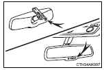
To ensure that the sensors operate properly, do not touch or cover them.
CAUTION
Do not adjust the position of the mirror while driving.
Doing so may lead to mishandling of the vehicle and cause an accident, resulting in death or serious injury.


Other materials:
Starting & charging
Preparation
Sst
Recomended tools
Equipment
...
Circuit description
The ignition switch provides circuit power and the ecm provides the circuit
ground that illuminates the mil.
Mil operation is checked visually:
it should be illuminated when the ignition is first turned on. If the mil is off
all of the time or on all of the time,
use the procedure below to ...
Circuit description
The door key lock and unlock switch is built in the door lock motor.
Wiring diagram
Inspection procedure
1 Check door lock
2 Check wire harness (tvip ecu door lock)
Disconnect the tvip ecu and door lock connectors.
check the continuity between the terminals of the t ...