Toyota Corolla (E120) 2002–2008 Repair Manual / Audio & visual / Antenna cord sub–assy
Toyota Corolla (E120): Antenna cord sub–assy
Replacement
Hint
: components:
1. Remove instrument panel sub–assy upper
Hint
:
- refer to the procedure until the step, ”remove instrument panel sub–assy upper” of instrument panel sub–assy lower.
- Remove the related parts as long as the antenna cord sub–assy can be removed.
2. Remove visor holder
Hint
:
- refer to the procedure until the step, ”remove visor holder” of roof headlining assy.
- Remove the parts related to the roof headlining assy in the range that antenna cord can be cut off.
3. Remove sun roof opening trim moulding (w/ sliding roof)
4. Disconnect antenna cord sub–assy
- Rear side: disconnect the connector and antenna cord plug.
- rear side: remove the 2 clamps.
- Front side: remove the 9 clamps.
5. Remove roof headlining assy
Notice
: do not bend the roof headlining assy.
6. Remove antenna cord sub–assy
- remove the antenna cord sub–assy from the roof headlining.
7. Install antenna cord sub–assy
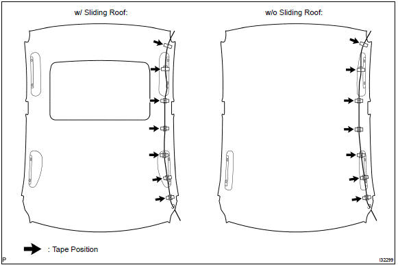
- tape the antenna cord sub–assy at the position of the roof headlining shown in the illustration.
Notice
:
- the antenna cord sub–assy should come to the center of the tape (100 mm(3.94 In.) X 25 mm(0.98 In.)) When taped.
- Try not to touch the adhesive side of the tape when taping.
- Install the roof headlining assy .
- engage the 9 clamps at the front side of antenna cord.
- connect the plug and connector at the rear side of antenna cord.
8. Install rear seat back assy (fixed type rear seat)
9. Install rear seat back assy (separated type rear seat)
10. Install bench type rear seat cushion assy( or 72–8)
11. Install instrument panel sub–assy upper
Hint
: refer to the procedure until the step, ”install instrument panel sub–assy upper” of instrument panel sub–assy lower.


Other materials:
Shift position uses
*: Shifting to the D position allows the system to select a gear suitable for
driving conditions. Setting the shift lever to the D position is recommended for
normal driving.
■Downshifting restrictions
The shift lever cannot be downshifted if the following speeds are exceeded.
mph (km ...
Disabling the TRAC system
If the vehicle gets stuck in mud, dirt or snow, the TRAC system may reduce power
from the engine to the wheels. Pressing
to turn the system off may make it
easier for you to rock the vehicle in order to free it.
To turn the TRAC system off, quickly press and release
.
The “TRAC OFF” ind ...
Deleting the contact data
For PBAP compatible Bluetooth® phones, this function is available when “Automatic
Contact/History Transfer” is set to off. 1 Select “Delete Contacts”.
2 Select the desired contact and select “Delete”.
3 Select “Yes” when the confirmation screen appears.
■ Deleting the con ...