Toyota Corolla (E120): Adjustment
1. Headlight aim only
- place the vehicle in the following conditions.
- The area around the headlight is not deformed.
- The vehicle is parked on a level surface.
- Tire inflation pressure is in the specified value .
- A driver is in the driver’s seat and the vehicle is in a state ready for driving (with a tank full).
- The vehicle has been bounced several times.
- check the headlight aiming.
- Prepare a thick white paper.
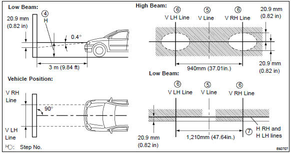
- Stand the paper perpendicular to the ground at the position 9.84 Ft away from the headlights.
- Ensure that the center line of the vehicle and the paper face forms a 90–degree angle as shown in the illustration.
- Draw a horizontal line (h line) on the paper, showing where the headlights should strike.
- Draw a vertical line (v line) to where the center line of the vehicle is to be.
- Draw 2 vertical lines to where the both headlights should strike (v rh and v lh lines).
- Draw a horizontal line (by connecting the both low beam center marks) to where the headlights should strike (h rh and h lh lines).
- Take appropriate measures to prevent any influence of other lights.
- Set the headlights leveling position to ”0” position and adjust the angle of the headlight axis.
Hint
: the h rh and h lh line is 0.4° Below the horizontal line (h line) of the light axis.
- Start the engine.
- Turn the headlights on.
- Check that the headlights properly strike the position shown in the illustration.
- If not, adjust the lights in the vertical direction.
Hint
:
- as shown in the illustration, adjust each aim of the rh and lh lights.
- When adjusting the headlight aim in the veatical direction: using adjusting bolt, adjust the headlight aim to be within the specified range.
Hint
: the optical aim moves upward when turning a screwdriver clockwise, while it moves downward when turning a screwdriver counterclockwise.


Other materials:
Supplemental restraint system
Preparation
Sst
Recomended tools
Equipment
...
Replacement
Hint:
installation is in the reverse order of the removal. But the installation is
indicated only when it has a point.
1. Remove radiator grille sub–assy
Remove the 2 bolts and clip.
using a screwdriver, remove the radiator grille.
Hint:
tape the screwdriver tip before use. ...
Overhaul
1. Drain brake fluid
Notice:
wash the brake fluid off immediately if it comes into contact with any painted
surface.
2. Remove air cleaner cap sub–assy
3. Remove brake master cylinder sub–assy
disconnect the brake fluid level switch connector from
master cylinder reservoir subâ ...