Toyota Corolla (E120) 2002–2008 Repair Manual / Exterior/interior trim / Roof drip side finish moulding center lh
Toyota Corolla (E120): Roof drip side finish moulding center lh
Replacement
Hint
:
- use the same procedures for the rh side and lh side.
- The installation procedures are the removal procedures in reverse order. However, only installation procedures requiring additional information are included.
1. Remove roof drip side finish moulding center lh
- Apply protective tape onto the circumference of the moulding for protection.
- using a remover for the roof moulding, release the engagements of the clips both in the front and rear ends of the moulding. Then remove the moulding.
Notice
:
- do not remove the clips.
- If clips are damaged during removal or removed accidentally, replace them.
2. Install roof drip side finish moulding clip no.1
Notice
: step 2 should be performed only when replacing the clips.
- remove the double–sided tape that remains on the mounting surface of the body, and then clean the surface with white gasoline.
- using a heat light, heat the clip installation surfaces of the body.
Heating temperature:
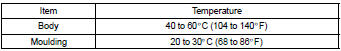
Notice
: do not heat the body and moulding excessively.
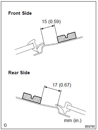
- set new clips in the positions as shown in the illustration,
and press–fit those clips by hand to install them.
Hint
: clips for the roof drip side finish moulding are supply parts.
- after press–fitting the clips, wait at last 30 minutes. Then install the moulding.
Hint
:
- initial hardening time: 30 minutes
- prefect hardening time: 24 hours


Other materials:
Overhaul
1. Inspect 1st gear thrust clearance
Using a feeler gauge, measure the 1st gear thrust clearance.
Standard clearance:
0.10 – 0.40 Mm (0.0039 – 0.0157 In.)
2. Inspect 2nd gear thrust clearance
Using a dial indicator, measure the 2nd gear thrust clearance.
Standard clearan ...
Mechanical system tests
1. Perform mechanical system tests
Measure the stall speed.
The object of this test is to check the overall performance of the transaxle
and engine by measuring
the stall speeds in the d and r positions.
Notice:
Do the test at normal operating atf temperature 50 to 80 °c (122 to
...
Pre–check
1. Selecting compass display mode
the compass switch allows you to select the display or non–display
mode of the compass.
2. Setting zone
deviation between the ”magnetic north” and ”actual north” differs
depending on the location. Therefore,
adjustment of the ...