Toyota Corolla (E120): Replacement
Hint
: components:
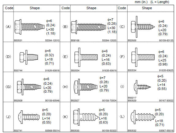
1. Table of bolt, screw and nut
N
otice
: be sure to tape the tip of the screwdriver when using it to disengage the meshing of the clips and claws.
Hint
: indicate the bolts, screws and nuts, which are necessary for installation and removal of the instrument panel, in the illustration and the text with alphabets.
2. Precaution
3. Separate battery negative terminal
4. Place front wheels facing straight ahead
5. Remove horn button assy
6. Remove steering wheel assy
sst 09950–50013 (09951–05010, 09952–05010, 09953–05020, 09954–05021)
7. Remove meter hood sub–assy
- Remove the clip.
- using a screwdriver, disengage the 7 claws, then remove the meter hood sub–assy.
Hint
: tape the screwdriver tip before use.
8. Remove combination meter assy
- Remove the screw<l>.
- disengage the 2 claws as shown in the illustration.
- disconnect the connector, then remove the combination meter assy.
9. Remove instrument panel register assy no.1
- Using a moulding remover, disengage the 4 claws, then remove the instrument panel register assy no.1.
10. Remove instrument panel register assy no.3
11. Remove floor shift shift lever knob sub–assy (m/t transaxle)
12. Remove console panel upper
- Using a screwdriver, disengage the 6 claws.
Hint
: tape the screwdriver tip before use.
- disconnect the connector, then remove the console panel upper.
13. Remove heater control knob
14. Remove instrument cluster finish panel
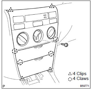
- Remove the screw<j>.
- using a screwdriver, disengage the 4 clips and 4 claws, then remove the instrument cluster finish panel.
Hint: tape the screwdriver tip before use.
- disconnect the connectors.
Notice
: do not pull the lid of auxiliary box.
15. Remove instrument cluster finish panel sub–assy center
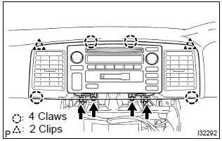
- Remove the 4 screws<k>.
- using a screwdriver, disengage the 2 clips and 4 claws, then remove the instrument cluster finish panel sub–assy center with radio receiver assy.
Hint
: tape the screwdriver tip before use.
- disconnect the connectors.
16. Remove glove compartment door assy
- Remove the screw<i> from the glove compartment door stopper sub–assy.
- deform the upper part of the glove compartment door assy to release the stoppers.
- pull the glove compartment door assy upward to remove it.
17. Remove front pillar garnish lh
- Disengage the clip.
- pull the front pillar garnish lh upward and disengage the 2 claws, then remove the front pillar garnish lh.
18. Remove front pillar garnish rh
19. Separate passenger airbag connector
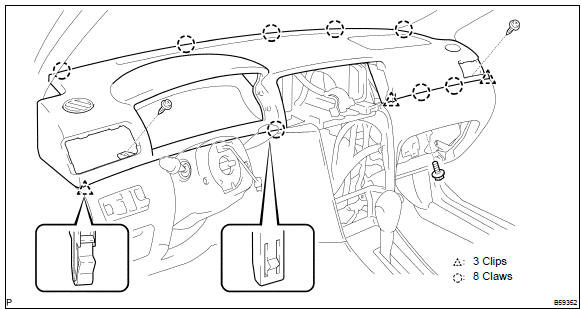
20. Remove instrument panel sub–assy upper
- remove the bolt<d> and 2 screws<j>.
- using a moulding remover, disengage the 3 clips and 8 claws.
- remove the instrument panel sub–assy upper.
21. Remove heater control & accessory assy
22. Remove steering column cover
23. Remove headlamp dimmer switch assy
24. Remove windshield wiper switch assy
25. Remove glove compartment door stopper sub–assy
- Disengage the clip, then remove the glove compartment door stopper sub–assy.
26. Remove parking brake hole cover sub–assy
- Using a screwdriver, disengage the 4 claws, then remove the parking brake hole cover sub–assy.
Hint
: tape the screwdriver tip before use.
27. Remove console box carpet
28. Remove console box sub–assy rear (m/t transaxle)
29. Remove console box sub–assy rear
- A/t transaxle: remove the 2 bolts<f>, 4 screws<j> and console box sub–assy rear.
- m/t transaxle: remove the 2 bolts<f>, 2 screws<j> and console box sub–assy rear.
30. Remove front door scuff plate lh
- Using a screwdriver, disengage the 7 claws, then remove the front door scuff plate lh.
Hint
: tape the screwdriver tip before use.
31. Remove front door scuff plate rh
32. Remove cowl side trim board lh
- Remove the clip.
- disengage the clip, then remove the cowl side trim board lh.
33. Remove cowl side trim board rh
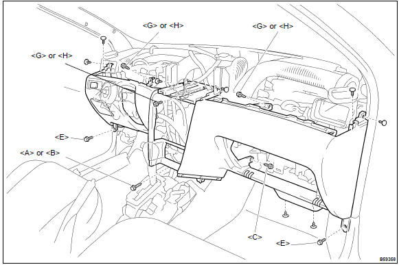
34. Remove instrument panel sub–assy lower
- disconnect the dlc3 connector.
- remove the hood lock control lever.
- remove the 3 screws<g> or <h>.
- remove the 2 bolts<e>.
- remove the bolt<a> or <b>.
- remove the bolt<c>.
- remove the 8 clips and instrument panel sub–assy lower.
35. Remove instrument panel box
36. Remove instrument panel box spring
37. Install heater control & accessory assy(see
38. Install instrument panel sub–assy upper
- install the instrument panel sub–assy upper.
- install the bolt<d> and 2 screws<j>.
Torque: bolt <d>: 20 nvm (204 kgfvcm, 15 ftvlbf)
39. Install instrument cluster finish panel sub–assy center
40. Center spiral cable
41. Install steering wheel assy
42. Inspect steering wheel center point
43. Inspect horn button assy
44. Install horn button assy
45. Inspect srs warning light


Other materials:
Torque converter clutch and drive plate (atm)
Inspection
1. Inspect torque converter clutch assy
Inspect the one–way clutch.
Set sst into the inner race of the one–way clutch.
Sst 09350–32014 (09351–32010)
set sst so that it fits in the notch of the converter
hub and outer race of the one–way clutch.
...
Front passenger occupant classification
system
Your vehicle is equipped with a front passenger occupant
classification system. This system detects the conditions of
the front passenger seat and activates or deactivates the front
passenger airbag and seat cushion airbag in the front passenger
side.
System components
SRS warning light
Front pa ...
Types of child restraints
Child restraint systems are classified into the following 3 types according to
the age and size of the child:
► Rear facing - Infant seat/convertible seat
► Forward facing - Convertible seat
► Booster seat
■Selecting an appropriate child restraint system
●U ...