Toyota Corolla (E120): Precaution
Caution
:
- the corolla is equipped with srs, which comprises a driver airbag, front passenger airbag and side airbag. Failure to carry out service operations in the correct sequence could cause the srs to unexpectedly deploy during servicing, possibly leading to a serious accident. Further, if a mistake is made in servicing the srs, it is possible that the srs may fail to operate when required. Before performing servicing (including removal or installation of parts, inspection or replacement), be sure to read the following items carefully, then follow the correct procedures described in the repair manual.
- Work must be started 90 seconds after the ignition switch is turned
to the ”lock” position and
the negative (–) terminal cable is disconnected from the battery.
(The srs is equipped with a back–up power source so that if work is started within 90 seconds from disconnecting the negative (–) terminal cable of the battery, the srs may be deployed.)
- Do not expose the horn button assy, instrument panel passenger airbag assy, airbag sensor assy center, airbag front sensor, front seat airbag assy, side airbag sensor assy or seat position airbag sensor directly to hot air or flames.
Notice
:
- malfunction symptoms of the srs are difficult to confirm, so the dtcs become the most important source of information when troubleshooting. When troubleshooting the srs, always inspect the dtcs before disconnecting the battery.
- Even in cases of a minor collision where the srs does not deploy, the horn button assy, instrument panel passenger airbag assy, airbag sensor assy center, airbag front sensor, front seat airbag assy, side airbag sensor assy and seat position airbag sensor should be inspected .
- Before repairs, remove the airbag sensor if shocks are likely to be applied to the sensor during repairs.
- Never use srs parts from another vehicle. When replacing parts, replace them with new parts.
- Never disassemble and repair the horn button assy, instrument panel passenger airbag assy, airbag sensor assy center, airbag front sensor, front seat airbag assy, side airbag sensor assy or seat position airbag sensor in order to reuse it.
- If the horn button assy, instrument panel passenger airbag assy, airbag sensor assy center, airbag front sensor, front seat airbag assy, side airbag sensor assy, seat position airbag sensor has been dropped, or if there are cracks, dents or other defects in the case, bracket or connector, replace it with a new one.
- Use a volt/ohmmeter with high impedance (10 kw/v minimum) for troubleshooting the system’s electrical circuits.
- Information labels are attached to the periphery of the srs components. Follow the instructions on the notices.
- After work on the srs is completed, perform the srs warning light check .
- When the negative (–) terminal cable is disconnected from the battery, the memory of the clock and audio system will be canceled. So before starting work, make a record of the contents memorized in the audio memory system. When work is finished, reset the audio systems as they were before and adjust the clock. To avoid erasing the memory in each memory system, never use a back–up power supply from outside the vehicle.
- If the vehicle is equipped with a mobile communication system, refer to the precaution in the introduction section.
1. Srs connectors
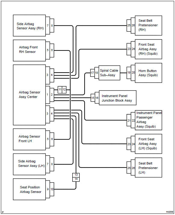
- All connectors in the srs are colored in yellow to distinguish them from other connectors. Connectors having special functions and specifically designed for the srs are used in the locations shown on the previous page to ensure high reliability. These connectors use durable gold–plated terminals.
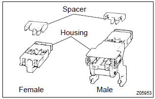
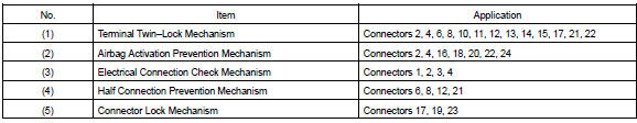
- Terminal twin–lock mechanism: each connector has a two–piece component consisting of a housing and a spacer. This design enables the terminal to be locked securely by two locking devices (the retainer and the lance) to prevent terminals from coming out.
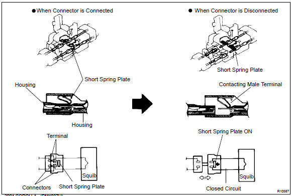
- Airbag activation prevention mechanism: each connector contains a short spring plate. When the connector is disconnected, the short spring plate automatically connects positive (+) terminal and negative (–) terminal of the squib.
Hint
: the type of connector is shown in the diagram on the previous page.
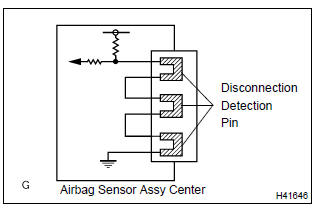
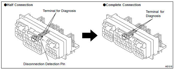
- Electrical connection check mechanism: this mechanism electrically checks that connectors are connected correctly and completely. The electrical connection check mechanism is designed so that the disconnection detection pin connects with the diagnosis terminals when the connector housing lock is locked.
Hint
: the connectors shown in this illustration are connectors, ”1”, ”2”, ”3” and ”4” in step 1.
- Half connection prevention mechanism: if the connector is not completely connected, the connector is disconnected due to the spring operation to the extent that no continuity exists.
- Connector lock mechanism: locking the connector lock button securely connects the connector.

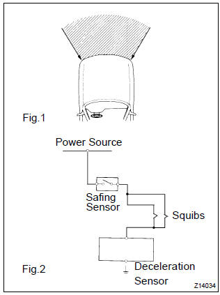
- When the vehicle is involved in a frontal collision in the hatched area (fig. 1) And the shock is larger than the predetermined level, the srs is activated automatically. A safing sensor is designed to go on at a smaller deceleration rate than the airbag sensor. As illustrated in fig. 2, Ignition is caused when current flows to the squib, which happens when a safing sensor and the deceleration sensor go on simultaneously. When a deceleration force acts on the sensors, 2 squibs in the driver airbag and front passenger airbag ignite and generate gas. The gas discharging into the driver airbag and front passenger airbag rapidly increases the pressure inside the bags, breaking open the horn button assy and instrument panel. Bag inflation then ends, and the bags deflate as the gas is discharged through discharge holes at the bag’s rear or side.
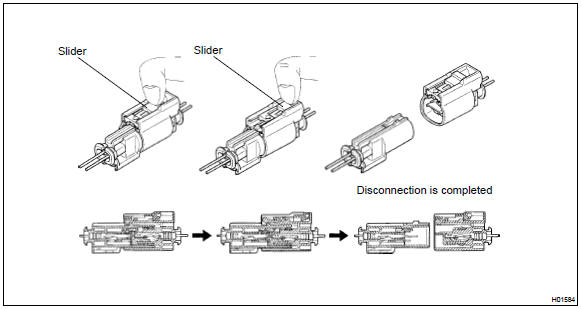
2. Disconnection of connector front seat airbag assy
- Place a finger on the slider.
- slide the slider to release lock.
- disconnect the connector.
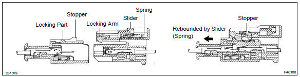
3. Connection of connector for front seat airbag assy
- align a lock part of male connector and a slider of female connector in the same direction as shown in the illustration, fit in them without rubbing.
- be sure to insert until they are locked. After fitting in, pull
them slightly to check that they are locked.
(When locked, make sure that the outer returns to its original position and sound at the time of fitting in can be heard.)
Hint
:
- as the slider slides, do not touch it.
- Be careful not to deform the release board. If the release board is deformed, replace it with a new one.
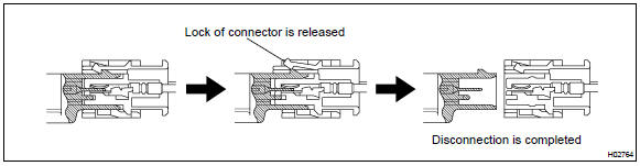
4. Disconnection of airbag front sensor and side airbag sensor
- while holding both flank sides of the outer, slide the outer in the direction shown by an arrow.
- release the lock of the connectors, then disconnect the connectors.
Hint
: be sure to hold both flank sides of the outer. If holding the top and bottom sides, it will obstruct disconnection.
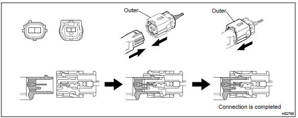
5. Connection of connectors for airbag front sensor and side airbag sensor
- align the male connector (on the side of sensor) with female connector in the same direction as shown in the illustration and fit them in without rubbing.
- as they are fitted in, the outer slides rearward. Press it until
the outer returns to its original position
again.
If fitting stops half way, connectors will separate.
- be sure to insert until they are locked. After fitting in, pull
them slightly to check that they are locked.
(When locked, make sure that the outer returns to its original position and sound at the time of fitting in can be heard.)
Hint
:
- do not fit in while holding the outer.
- When fitting in, the outer slides. Do not touch it.


Other materials:
Deleting call histories
Select “Delete Call History” using
. ● Deleting outgoing call history
1 Select “Outgoing Calls” using .
2 Select the desired phone number using
and press
(YES).
To delete all outgoing call history data, press
(ALL) and then press
(YES).
● Deleting incoming call histo ...
Diagnosis system
Description
when troubleshooting obd ii vehicles, the only difference
from the usual troubleshooting procedure
is that you need to connect an obd ii scan tool complying
with sae j1987 or a hand–held tester to the
vehicle, and read off various data output from the
vehicle‚Ä ...
Inspection procedure
Hint:
start the inspection from step 1 in case of using the hand–held tester and start
from step 2 in case of not
using the hand–held tester.
1 Perform active test by hand–held tester(abs motor relay)
Check the operation sound of the abs motor individually when operaing it
with the ...