Toyota Corolla (E120) 2002–2008 Repair Manual / Introduction / Repair instruction / Precaution / Electronic control
Toyota Corolla (E120): Electronic control
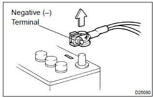
- Removal and installation of battery terminal
- before performing electrical work, disconnect the battery negative (–) terminal cable beforehand so as to prevent burnt–out damage by short.
- When disconnecting and installing the terminal cable, turn the ignition switch and lighting switch off, and loosen the terminal nut completely. Perform these operations without twisting or prying the terminal.
- When the battery terminal is removed, all the memories
of the clock, radio, dtcs, etc. Will be erased.
So before removing it, check them and note them down.
- Handling of electronic parts
- do not open the cover or case of the ecu unless absolutely necessary (if the ic terminals are touched, the ic may be destroyed by static electricity).
- To disconnect electronic connectors, pull the connector itself, not the wires.
- Be careful not to drop electronic components, such as sensors or relays. If they are dropped on a hard floor, they should be replaced and not be reused.
- When cleaning the engine with steam, protect the electronic components, air filter and emission–related components from water.
- Never use an impact wrench to remove or install temperature switches or temperature sensors.
- When checking the continuity at the wire connector, insert the tester probe carefully to prevent terminals from bending.


Other materials:
Circuit description
The p/t squib (rh) circuit consists of the airbag sensor assy center and seat
belt pretensioner (rh).
It causes the srs to deploy when the srs deployment conditions are satisfied.
Dtc b0130/63 is recorded when a short is detected in the p/t squib (rh) circuit.
Wiring diagram
...
Evap monitor (vacuum pressure monitor) (continued)
Preconditions
The monitor will not run unless:
mil is off.
Fuel level is approximately 1/2 to 3/4.
Altitude is 7800 feet (2400 m) or less.*
Engine coolant temperature (ect) is between 40°f and 95°f (4.4 °C and 35
°C).
Intake air temperature (iat) is between 40°f and 95 ...
Replacement
1. Work for preventing gasoline from spilling out
2. Remove front wheels
3. Remove engine under cover rh
4. Remove engine under cover lh
5. Drain coolant
6. Remove cylinder head cover no.2
Remove the 2 nuts, 2 clips and cylinder head cover.
7. Disconnect radiator hose inlet
&nb ...