Toyota Corolla (E170) 2014–2019 Owners Manual / Driving / Driving procedures / Engine (ignition) switch (vehicles with a smart key system) / Changing engine switch modes
Toyota Corolla (E170): Changing engine switch modes
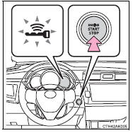
Modes can be changed by pressing the engine switch with the brake pedal (continuously variable transmission) or clutch pedal (manual transmission) released. (The mode changes each time the switch is pressed.)
► Vehicles without a multi-information display Off*
The emergency flashers can be used.
The smart key system indicator light (green) is off.
ACCESSORY mode
Some electrical components such as the audio system can be used.
The smart key system indicator light (green) flashes slowly.
IGNITION ON mode
All electrical components can be used.
The smart key system indicator light (green) flashes slowly.
*: Vehicles with a continuously variable transmission: If the shift lever is in a position other than P when turning off the engine, the engine switch will be turned to ACCESSORY mode, not to off.
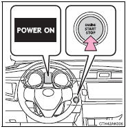
► Vehicles with a multi-information display Off*
The emergency flashers can be used.
The multi-information display will not be displayed.
ACCESSORY mode
Some electrical components such as the audio system can be used.
“POWER ON” will be displayed on the multi-information display.
IGNITION ON mode
All electrical components can be used.
“POWER ON” will be displayed on the multi-information display.
*: Vehicles with a continuously variable transmission: If the shift lever is in a position other than P when turning off the engine, the engine switch will be turned to ACCESSORY mode, not to off.


Other materials:
Riding with children
Observe the following precautions
when children are
in the vehicle.
Use a child restraint system
appropriate for the child,
until the child becomes
large enough to properly
wear the vehicle's seat belt.
It is recommended that children
sit in the rear seats to
avoid accidental contact
with the ...
Windshield wipers and washer
Operating the wiper lever
The wiper operation is selected by moving the lever as follows. When intermittent
windshield wiper operation is selected, the wiper interval can be also adjusted.
1 Intermittent windshield wiper operation
2 Low speed windshield wiper operation
3 High speed windshield ...
Inspection procedure
1 Inspect shift solenoid valve(s1)
Remove the shift solenoid valve s1.
measure the resistance according to the value(s) in the
table below.
Standard:
Connect the positive (+) battery lead to the solenoid connector
terminal, and the negative (–) battery lead to the
solenoid ...