Toyota Corolla (E170) 2014–2019 Owners Manual / For safety and security / For safe use / Before driving
Toyota Corolla (E170): Before driving
Floor mat
Use only floor mats designed specifically for vehicles of the same model and model year as your vehicle. Fix them securely in place onto the carpet.
1 Insert the retaining hooks (clips) into the floor mat eyelets.
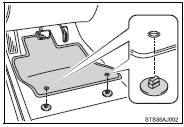
2 Turn the upper knob of each retaining hook (clip) to secure the floor mats in place.
*: Always align the  marks.
The shape of the retaining hooks (clips) may differ from that shown in the illustration.
CAUTION
Observe the following precautions.
Failure to do so may cause the driver’s floor mat to slip, possibly interfering with the pedals while driving. An unexpectedly high speed may result or it may become difficult to stop the vehicle, leading to an accident, or leading to death or a serious injury.
■When installing the driver’s floor mat
●Do not use floor mats designed for other models or different model year vehicles, even if they are Toyota Genuine floor mats.
●Only use floor mats designed for the driver’s seat.
●Always install the floor mat securely using the retaining hooks (clips) provided.
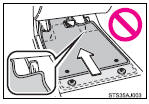
●Do not use two or more floor mats on top of each other.
●Do not place the floor mat bottom-side up or upside-down.
■Before driving
●Check that the floor mat is securely fixed in the correct place with all the provided retaining hooks (clips). Be especially careful to perform this check after cleaning the floor.
●With the engine stopped and the shift lever in P (automatic transmission or continuously variable transmission) or N (manual transmission), fully depress each pedal to the floor to make sure it does not interfere with the floor mat.


Other materials:
Replacement
1. Drain brake fluid
Notice:
wash the brake fluid off immediately if it comes into contact with any painted
surface.
2. Remove front wheel rh
3. Remove front fender liner rh
4. Remove brake actuator with bracket
turn the latch of the actuator connector to disconnect the
connector. ...
Precaution
1. Precaution of headlight bulb replacement
if even a thin film of oil is left on the surface of the halogen
lamp, its service life will be shortened because
the lamp will be burn at a higher temperature.
handle any halogen lamp with great care. Dropping, hitting or
damagin ...
Dialing
1 Display the phone screen. 2 Select the “Dial Pad” tab and enter a phone number.
To delete the input phone number, select
.
For the first digit, you can enter “+” by selecting “*” for a while.
3 Press the switch on the steering
wheel or select . ...