Toyota Corolla (E120): Basic inspection
- Resistance measuring condition of electronic parts
- unless stated, all resistance is measured at an ambient temperature of 20 c (68 °F). As the resistance may be outside the specifications if measured at high temperatures immediately after the vehicle has been running, measurements should be made when the engine has cooled down.
- Handling of connector
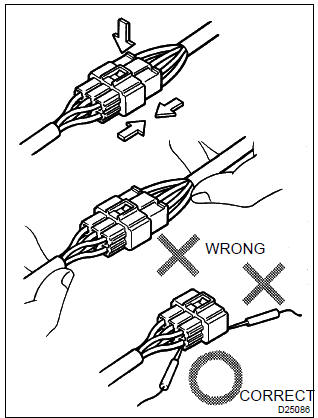
- when removing the connector with lock, press the connector in the direction of the engagement and remove the lock by lightly pressing the lock claw.
- When removing the connector, do not hold the harness, but hold the connector.
- Before connecting the connector, check that there is no deformation, damage or missing terminals.
- The connector with a lock should be securely connected until it makes a ”click” sound.
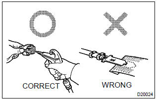
- When checking the connector with a toyota electrical tester, check it from the backside (harness side) of the connector using a mini test lead.
Notice
:
- as a water proof connector cannot be checked from the backside, check by connecting the sub–harness.
- Do not damage the terminals by moving the inserted tester needle.
- Connector checking points
- checking when the connector is connected: by holding the connector, check the inserted condition and locking efficiency (engaged condition).
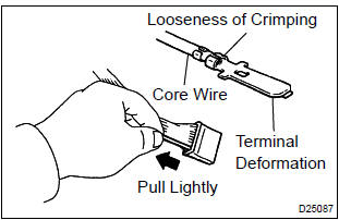
- Checking when the connector is removed:
check by lightly pulling the wire harness (missing
terminal, terminal crimping condition, core wire
break).
Check visually for any rust, metal particles, water and bent terminals (rust, mixing of foreign object, terminal deformation).
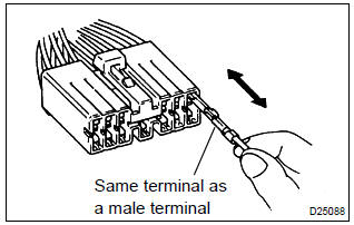
Notice
: when testing a gold–plated female terminal, always use a gold–plated male terminal.
- Checking of the contact pressure of the terminal:
prepare a spare male terminal.
Insert it into a female terminal, check the engaged condition and sliding resistance.
- Repair method of connector terminal
- if there is on the contact point, clean the contact point using an air gun or shop rag. However, never polish the contact point using sand paper as the platings may come off.
- In case of abnormal contact pressure, replace the female terminal. However, if a male terminal is gold– plated (gold color), use gold–plated female terminal and if it is silver–plated (silver color), use silver– plated female terminal.
- Handling of wire harness
- when removing the wire harness, check the positioning of the wiring and clamping before starting work in order to be able to restore it correctly.
- Never twist, pull or loosen the wire harness more than necessary.
- Never allow the wire harness to come into contact with a high–temperature, rotating, moving, vibrating or sharp (edge of the panel, tip of the screw, etc.) Part.
- When installing parts, never let the wire harness be interfered with.
- Never cut or break the cover of the wire harness. If one is cut or broken, replace it or securely repair it with electrical tape.


Other materials:
Seat belt warning lamp for front passenger’s seat
does not flash
Wiring diagram
Inspection procedure
1 Inspect combination meter assy
Ground terminal c9–11 on the combination meter side.
check that the warning lightlights up.
Ok: warning light lights up.
2 Inspect passenger seat belt warning lamp assy
Ground terminal c9– ...
Inspection procedure
1 Check security indicator light
Set the system in 30 seconds after filliping the security indicator to
check if the alarm is triggered.
2 Check glass breakage sensor ecu (glass breakage sensor)
Check the continuity and voltage of the glass breakage
sensor ecu, as shown in th ...
Replacement
Hint:
installation is in the reverse order of the removal. But the installation is
indicated only when it has a point.
1. Remove radiator grille sub–assy
Remove the 2 bolts and clip.
using a screwdriver, remove the radiator grille.
Hint:
tape the screwdriver tip before use. ...