Toyota Corolla (E170) 2014–2019 Owners Manual / Interior features / Basic Operations (Multimedia system) / Basic Audio Operations
Toyota Corolla (E170): Basic Audio Operations
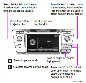
Basic audio operations and functions common to each mode are explained in this section.
Operating the multimedia system
Random playback
Select  to change on/off.
Repeat play
Select  to change on/off.
■Using cellular phones
Interference may be heard through the multimedia system's speakers if a cellular phone is being used inside or close to the vehicle while the multimedia system is operating.
CAUTION
■Laser produc
t This product is a class 1 laser product.
Do not open the cover of the player or attempt to repair the unit yourself.
Refer servicing to qualified personnel.
●Laser products • Do not take this unit apart or attempt to make any changes yourself. This is an intricate unit that uses a laser pickup to retrieve information from the surface of compact discs. The laser is carefully shielded so that its rays remain inside the cabinet. Therefore, never try to disassemble the player or alter any of its parts since you may be exposed to laser rays and dangerous voltages.
• This product utilizes a laser.
Use of controls or adjustments or performance of procedures other than those specified herein may result in hazardous radiation exposure.
THE USE OF OPTICAL INSTRUMENTS WITH THIS PRODUCT WILL INCREASE EYE HAZARD.
NOTICE
■To prevent battery discharge
Do not leave the multimedia system on longer than necessary when the engine is off.
■To avoid damaging the multimedia system
Take care not to spill drinks or other fluids on the multimedia system.


Other materials:
Inspection procedure
1 Check p squib circuit(airbag sensor assy center – instrument
panel passenger airbag assy)
Disconnect the negative (–) terminal cable from the battery,
and wait at least for 90 seconds.
disconnect the connector between the airbag sensor
assy center and the instrument panel ...
Floor shift cable transmission control
shift (atm)
Replacement
1. Precaution
2. Disconnect battery negative terminal
3. Remove parking brake hole cover sub–assy
4. Remove console panel upper
5. Remove console box carpet
6. Remove console box sub–assy rear
7. Remove air bag sensor assy center
8. Disconnect oxygen sensor connector
...
Window lock switch
Press the switch to lock the passenger window switches.
Use this switch to prevent children from accidentally opening or closing a passenger
window.
■The power windows can be operated when
► Vehicles without a smart key system
The engine switch is in the “ON” position.
υ ...