Toyota Corolla (E120) 2002–2008 Repair Manual / Supplemental restraint system / Spiral cable sub–assy
Toyota Corolla (E120): Spiral cable sub–assy
Components
Replacement
Hint
: components:
1. Precaution
2. Disconnect battery negative terminal
3. Place front wheels facing straight ahead
- check that the front wheels are facing straight ahead.
4. Remove horn button assy
5. Remove steering wheel assy
sst 09950–50013 (09951–05010, 09952–05010, 09953–05020, 09954–05021)
6. Remove steering column cover
7. Remove spiral cable sub–assy
- Disconnect the airbag connector and the connector from the spiral cable sub–assy.
- release the 3 claws and remove the spiral cable sub– assy.
8. Inspect spiral cable sub–assy
- if the following condition is identified, replace the spiral cable sub–assy with a new one.
Condition
: scratches or cracks on the connector cracks, dents or chipping of the spiral cable sub–assy
9. Place front wheels facing straight ahead
- check that the front wheels are facing straight ahead.
10. Install spiral cable sub–assy
- set the turn signal switch in neutral position.
Notice
: make sure of the neutral position since the pin of the turn signal switch may be snapped.
- engage the 3 claws and install the spiral cable sub–assy.
Notice
: when replacing the spiral cable sub–assy with a new one, remove the lock pin before installing the handle.
- connect the airbag connector and the connector connecting to the spiral cable sub–assy.
- install the steering column cover with the 3 screws.
11. Center spiral cable
- check that the ignition switch is turned to off.
- check that the battery negative terminal is disconnected.
Notice
: do not start the operation for 90 seconds after removing the terminal.
- Turn the cable counterclockwise by hand until it becomes harder to turn.
Hint
: the cable will rotate about 2.5 Turns to either left or right of the center.
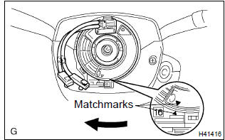
- Then rotate the cable clockwise about 2.5 Turns to align the marks.
12. Install steering wheel assy
torque: 50 nvm (510 kgfvcm, 37 ftvlbf)
13. Install horn button assy
torque: 8.8 Nvm (90 kgfvcm, 78 in.Vlbf)
14. Inspect horn button assy
15. Inspect srs warning light


Other materials:
Circuit description
The vapor pressure sensor and the vsv for the canister closed valve (ccv) are
used to detect abnormalities
in the evaporative emission control system. The ecm decides whether there is an
abnormality in the evaporative
emission control system based on the vapor pressure sensor signal.
Dtc p0 ...
Inspection procedure
1 Inspect stop lamp switch assy
Check that the stop light lights up when brake pedal is depressed and
turns off when the brake pedal
is released.
2 Inspect skid control ecu terminal voltage(stp terminal)
Disconnect skid control ecu connector.
measure voltage between termina ...
Oil filter sub–assy
Replacement
Caution:
prolonged and repeated contact with mineral oil will result in the
removal of natural fats from
the skin, leading to dryness, irritation and dermatitis. In addition, used
engine oil contains potentially
harmful contaminants which may cause skin cancer.
Exercise ...