Toyota Corolla (E120) 2002–2008 Repair Manual / Diagnostics / Combination meter / Seat belt warning lamp for front passenger’s seat
does not flash
Toyota Corolla (E120): Seat belt warning lamp for front passenger’s seat does not flash
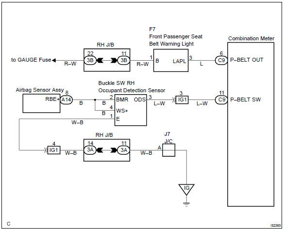
Wiring diagram
Inspection procedure
1 Inspect combination meter assy
- Ground terminal c9–11 on the combination meter side.
- check that the warning lightlights up.
Ok: warning light lights up.


2 Inspect passenger seat belt warning lamp assy
- Ground terminal c9–6 on the combination meter side.
- check that the warning lightlights up.
Ok: warning light lights up.

Check and replace combination meter assy
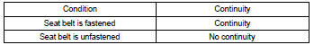
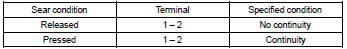
3 Inspect front seat inner belt assy rh
- Check continuity.
- Disconnect the front seat inner belt assy.
- Check the continuity in between terminals 1 and 2
of front seat inner belt assy rh.
Ok:

4 Inspect separate seat type front seat cushion pad
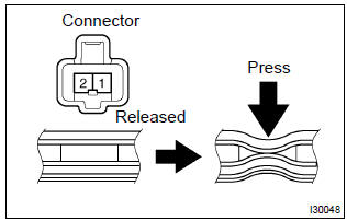
- Disconnect the separate type front seat cushion pad.
- check continuity separate type front seat cushion pad.

Repair or replace harness and connector


Other materials:
Rear view monitor system precautions
■ Area displayed on screen
The rear view monitor system displays an image of the view from the bumper of
the rear area of the vehicle.
To adjust the image on the rear view monitor system screen.
• The area displayed on the screen may vary according to vehicle orientation
conditions.
...
Inspection procedure
1 Check operation(stop lamp swtich assy)
Check that the stop light comes on when the brake pedal is depressed,
and turns off when the brake
pedal is released.
2 Input signal check
See input signal check on page 05–745.
check the indicator light when the brake pedal ...
Replacement
Hint: components:
1. Precaution
2. Disconnect battery negative terminal
3. Remove air bag front rh sensor
Disconnect the connector from the airbag front rh sensor.
remove the 2 bolts and airbag front rh sensor.
4. Inspect air bag front rh sensor
5. Install air bag front rh ...