Toyota Corolla (E120) 2002–2008 Repair Manual / Exhaust / Removal & installation and disassembly & reassembly
Toyota Corolla (E120): Removal & installation and disassembly & reassembly
1. Remove oxygen sensor
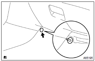
- Remove a clip and tear off the floor mat.
- disconnect a oxygen sensor connector.
- Remove the oxygen sensor.
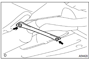
2. Remove tail pipe assy
- Remove 2 bolts, 2 springs and tail pipe assy.
3. Remove floor panel brace front
- Remove 2 nuts and the front floor panel brace front.
4. Remove exhaust pipe assy front
- Remove 2 bolts, 2 springs and exhaust pipe assy front.
5. Install exhaust pipe assy front
- using vernier calipers, measure the free length of the compression
spring.
Minimum length: 41.5 Mm (1.634 In.) Hint
: if the free length is less than minimum, replace the compression spring.
- install a new gasket on the exhaust manifold.
- install the exhaust pipe front with 2 bolts and 2 springs.
Torque: 43 nvm (440 Kgf·cm, 32 ft·lbf)
6. Install floor panel brace front
- install the front panel brace front with 2 nuts.
Torque: 30 nvm (302 Kgf·cm, 22 ft·lbf)
7. Install tail pipe assy
- using vernier calipers, measure the free length of the compression
spring.
Minimum length: 38.5 Mm (1.516 In.) Hint
: if the free length is less than minimum, replace the compression spring.
- install a new gasket on the exhaust pipe front.
- install the exhaust tail pipe with 2 bolts and 2 springs.
Torque: 43 nvm (440 Kgf·cm, 32 ft·lbf)
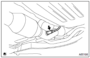
8. Install oxygen sensor

- Install the oxygen sensor to the exhaust pipe front.
Torque: 44 nvm (450 Kgf·cm, 33 ft·lbf)
- connect the oxygen sensor connector.
Hint
: after installing oxygen sensor, check that sensor wire is not twisted. If it is twisted, remove the oxygen sensor and reinstall it.
9. Check exhaust gas leak


Other materials:
Using a Bluetooth® Phone
The hands-free system is a function that allows you to use your cellular phone
without touching it.
This system supports Bluetooth®. Bluetooth® is a wireless data system that allows
the cellular phone to wirelessly connect to the hands-free system and make/receive
calls.
Before making a ph ...
Door control transmitter
Registration
1. Registration of recognition code
Hint:
the add mode is used to retain the already registered codes while
registering a new recognition code.
This mode is used when adding a transmitter. If the number of the registered
codes exceeds 4, the
previously registered code wi ...
Diagnostic trouble code chart
The inspection procedures are shown in the table below. This table allows
efficient and accurate troubleshooting
using the diagnostic trouble codes displayed in the diagnostic trouble code
chart. Proceed with
troubleshooting in accordance with the inspection procedures listed in the
diagnost ...