Toyota Corolla (E120) 2002–2008 Repair Manual / Supplemental restraint system / Supplemental restraint systems / On–vehicle inspection
Toyota Corolla (E120): On–vehicle inspection
1. Horn button assy (vehicles not involved in collision)
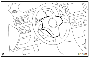
- Check the diagnostic system .
- visually check the following item with the horn button assy
(with airbag) installed in the vehicle.
Check cuts, minute cracks or marked discoloration on the horn button assy top surface and in the grooved portion.
2. Horn button assy(vehicle involved in collision and airbag is not deployed)
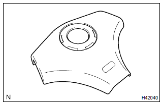
- Check the diagnostic system .
- visually check the following items with the horn button assy (with airbag) removed from the vehicle.
- Check cuts, minute cracks or marked discoloration on the horn button assy top surface and in the grooved portion.
- Check cuts and cracks in wire harness, and chipping in connectors.
- Check the deformation on the steering wheel.
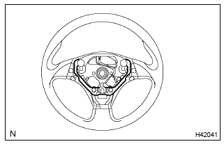
- Check the deformation on the horn button contact plate of the steering wheel assy.
Hint
: if the horn button contact plate of the steering wheel assy is deformed, never repair it. Always replace the horn button assy with a new one.
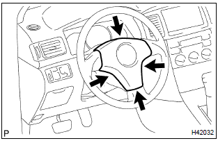
- There should be no interference between the horn button assy and steering wheel, and the clearance should be uniform all the way around when the new horn button assy is installed on the steering wheel.
Caution
: for removal and installation of the horn button assy, , and be sure to follow the correct procedure.
3. Horn button assy(vehicle involved in collision and airbag is deployed)
- check the diagnostic system .
- visually check the following item with the horn button assy (with
airbag) removed from the vehicle.
Check the damage on the spiral cable connector and wire harness.
Hint
: there should be no interference between the horn button assy and steering wheel, and the clearance should be uniform all the way around when the new horn button assy is installed on the steering wheel.
4. Instrument panel passenger airbag assy(vehicle not involved in collision)
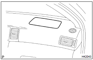
- Check the diagnostic system .
- visually check the following item with the instrument panel
passenger airbag assy installed in the vehicle.
Check cuts, minute cracks or marked discoloration on the instrument panel passenger airbag assy and instrument panel.
5. Instrument panel passenger airbag assy(vehicle involved in collision and airbag is not deployed)
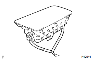
- Check the diagnostic system .
- visually check the following items with the instrument panel passenger airbag assy removed from the vehicle.
- Check cuts, minute cracks or marked discoloration on the instrument panel passenger airbag assy.
- Check cuts and cracks in wire harness, and for chipping in connectors.
- Check the deformation or cracks on the instrument panel and instrument panel reinforcement.
Hint
: if the instrument panel or instrument panel reinforcement is deformed or cracked, never repair it. Always replace it with a new one.
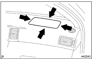
Caution
: for removal and installation of the instrument panel passenger airbag assy, , and be sure to follow the correct procedure.
6. Instrument panel passenger airbag assy(vehicle involved in collision and airbag is deployed)
- check the diagnostic system .
- visually check the following items with the instrument panel passenger airbag assy removed from the vehicle.
- Check the deformation or cracks on the instrument panel and instrument panel reinforcement.
- Check the damage on the connector and wire harness.
Hint
: if the instrument panel or instrument panel reinforcement is deformed or cracked, never repair it. Always replace it with a new one.
7. Front seat airbag assy(vehicle not involved in collision)
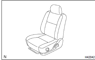
- Check the diagnostic system .
- visually check the following item with the front seat airbag
assy installed in the vehicle.
Check cuts, minute cracks or marked discoloration on the front seat airbag assy and the front seat assy.
8. Front seat airbag assy(vehicle involved in collision and airbag is not deployed)
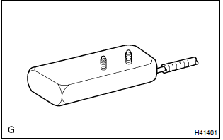
- Check the diagnostic system .
- visually check the following items with the front seat airbag assy removed from the front seat assy.
- Check cuts, minute cracks or marked discoloration on the front seat airbag assy.
- Check cuts and cracks in wire harness, and for chipping in connectors.
9. Airbag sensor assy center(vehicle not involved in collision)
- check the diagnostic system .
10. Airbag sensor assy center(vehicle involved in collision and airbag is not deployed)
- check the diagnostic system .
11. Airbag sensor assy center(vehicle involved in collision and airbag is deployed)
- replace the airbag sensor assy center
12. Airbag front sensor(vehicle not involved in collision)
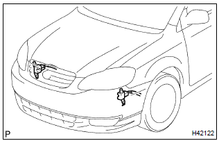
- Check the diagnostic system .
13. Airbag front sensor(vehicle involved in collision)
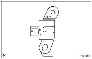
- Check the diagnostic system .
- if the front fender of the car or its periphery is damaged, visually check for damage to the airbag front sensor, which includes the following items even if the airbag was not deployed:
- cracks, dents or chips in the case
- cracks, dents, chipping and scratches in the connector
- peeling off of the label or damage to the serial number
14. Side airbag sensor assy(vehicle not involved in collision)
- check the diagnostic system .
15. Side airbag sensor assy(vehicle involved in collision and airbag is not deployed)
- check the diagnostic system .
16. Side airbag sensor assy(vehicle involved in collision and airbag is deployed)
- replace the front seat airbag assy and side airbag sensor assy (, 72–2).
17. Seat position airbag sensor(vehicles not involved in collision)
- check the diagnostic system .
18. Seat position airbag sensor(vehicle involved in collision)
- check the diagnostic system .
- visually check for damage to the seat position airbag sensor, which includes the following items even if the airbag was not deployed:
- cracks, dents or chips in the case
- cracks, dents, chipping and scratches in the connector
19. Wire harness and connector(vehicle not involved in collision)
- check the diagnostic system .
20. Wire harness and connector(vehicle involved in collision)
- check the diagnostic system .
- check breaks in all wires of the srs wire harness, and exposed conductors.
- check to see if the srs wire harness connectors are cracked or chipped.
Hint
: the srs wire harness is integrated with the instrument panel wire harness assembly. All the connectors in the system are standard yellow.
Other materials:
Inspection procedure
1 Check harness and connector(transmission control switch –
body ground)
Disconnect the transmission control switch connector of
shift lever assy.
measure the resistance according to the value(s) in the
table below.
Standard:
2 Inspect transmission control switch
M ...
Front suspension
Preparation
Sst
Recomended tools
Equipment
...
General maintenance
Listed below are the general
maintenance items that
should be performed at the
intervals specified in the
"Owner's Warranty Information
Booklet" or "Owner's
Manual Supplement/Scheduled
Maintenance Guide". It
is recommended that any
problem you notice should
be brought to the attention
of your Toyota ...


