
Toyota Corolla (E120) 2002–2008 Repair Manual / Diagnostics / Cruise control system / Actuator mechanical malfunction / Inspection procedure
Toyota Corolla (E120): Inspection procedure
1 Inspect cruise control actuator assy
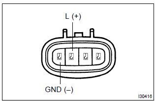
- Inspect the cruise control actuator arm locking operation.
- Turn the ignition switch to off.
- Disconnect the cruise control actuator assy connector.
- Connect the positive (+) lead from the battery to the terminal 3 (l) of cruise control actuator assy and the negative (–) lead to terminal 4 (gnd).
Notice
: do not connect the high tension cables to the wrong battery terminal. You will damage the cruise control actuator assy.
- Move the control plate by hand.
Ok: control plate does not move.
- inspect the cruise control actuator assy operation.
- Turn the ignition switch to off.
- Disconnect the cruise control actuator assy connector.
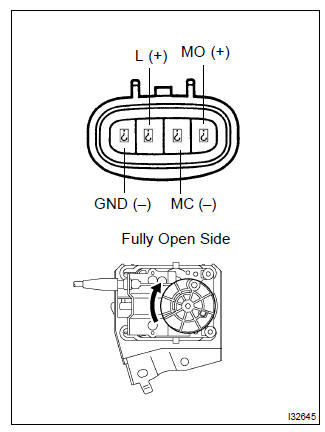
- Connect the positive (+) lead from the battery to terminals
1 (mo) and 3 (l) of cruise control actuator
assy, connect the negative (–) lead to terminals 2
(mc) and 4 (gnd) of cruise control actuator assy.
Ok: control arm moves to full open side.
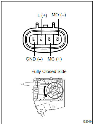
- Connect the positive (+) lead from the battery to terminals
2 (mc) and 3 (l) of cruise control actuator
assy, connect the negative (–) lead to terminals 1
(mo) and 4 (gnd) of cruise control actuator assy.
Ok: control arm moves to full close side.


2 Check harness and connector(between cruise control ecu assy and cruise control actuator assy)
- Check for open and short circuit in harness and connector between cruise control ecu assy and cruise control actuator assy (actuator motor)


Check and replace cruise control ecu assy


Other materials:
Sliding roof/convertible
Service data
Torque specification
Engine hood/door
Torque specification
Exterior/interior trim
Torque specification
Cruise control
Service data
Torque specification
...
Engine mechanical
Service data
Torque specification
...
Check short circuit
If the wire harness is ground shorted as shown in fig. 5,
Locate the section by conducting a resistance check with
the body ground in step (b).
Check the resistance with the body ground.
Disconnect connectors a and c and measure the
resistance between terminals 1 and 2 ...