Toyota Corolla (E120): Inspection procedure
1 Check door lock
- When the door does not operate manually, proceed to ”a”.
- when the door does not operate via the key, proceed to ”b”.


2 Inspect door lock control switch
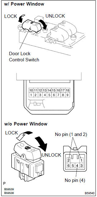
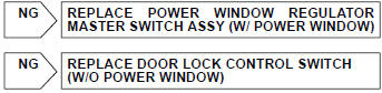
- W/ power window: remove the power window regulator master switch assy.
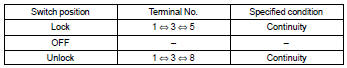
- Inspect the master switch (door lock control switch) continuity, as shown in the illustration and table.
Standard:
- W/o power window: remove the door lock control switch.
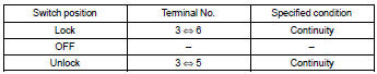
- Inspect the door lock control switch continuity, as shown in the illustration and table.
Standard:

3 Check wire harness (switch integration relay)
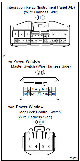
- W/ power window:
disconnect the power window regulator master switch
assy and integration relay connectors.
W/o power window: disconnect the door lock control switch and integration relay connectors.
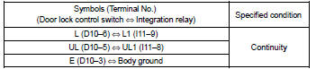
- check the continuity between the terminals of the power window regulator master switch assy or door lock control switch and integration relay connectors, as shown in the illustration and tables.
[W/ power window] standard (check for open):
![[W/o power window]](images/books/422/24/index.38.jpg)
[W/o power window] standard (check for open):
4 Inspect driver’s door lock
- Inspect the driver’s door lock key switch.
- inspect the driver’s door lock position switch.


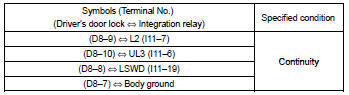
5 Check wire harness (driver’s door lock integration relay)
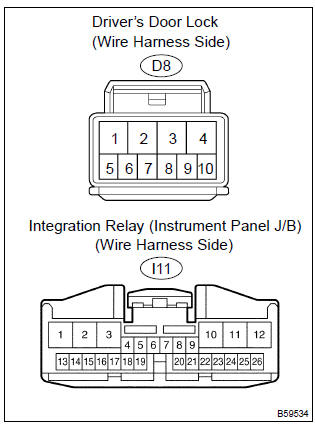
- Disconnect the driver’s door lock and integration relay connectors.
- check the continuity between the terminals of the driver’s door lock and integration relay connectors, as shown in the illustration and table.
Standard (check for open):

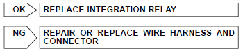
Replace integration relay


Other materials:
Inspection procedure
1 Inspect fuse(ecu–ig fuse)
Remove ecu–ig fuse from the instrument panel j/b.
check continuity of ecu–ig fuse.
Ok:
continuity
2 Inspect battery
Ok:
voltage: 10 – 14 v
3 Inspect skid control ecu connector(ig1 terminal voltage)
In case of using hand–held te ...
How to proceed with troubleshooting
1 Vehicle brought to workshop
2 Customer problem analysis
3 Check and clear dtcs and freeze frame data
4 Problem symptom confirmation
Symptom does not occur: go to
step 5
Symptom occurs: go to step 6
5 Symptom simulation
6 Dtc check
There is no
output: go to step 7
There is outp ...
Brake
On–vehicle inspection
1. Inspect brake line pipes and hoses
Hint:
work in a well–lighted area. Turn the front wheels fully to the
right or left before begining.
check all the brake lines and hoses for:
damage
wear
deformation
cracks
corrosion
leaks
bends
twi ...