Toyota Corolla (E120) 2002–2008 Repair Manual / Diagnostics / Supplemental restraint system / Seat position airbag sensor
malfunction / Inspection procedure
Toyota Corolla (E120): Inspection procedure
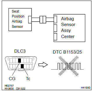
1 Check seat position air bag sensor
Sst 09843–18040
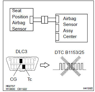
- Turn the ignition switch to on, and wait at least for 20 seconds.
- clear the dtc stored in memory .
- turn the ignition switch to lock, and wait at least for 20 seconds.
- turn the ignition switch to on, and wait at least for 20 seconds.
- check the dtc .
Ok: dtc b1153/25 is not output.
Hint
: codes other than code b1153/25 may be output at this time, but they are not relevant to this check.


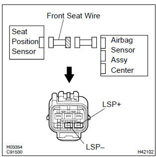
2 Check airbag sensor assy center connector
- Turn the ignition switch to lock.
- disconnect the negative (–) terminal cable from the battery, and wait at least for 90 seconds.
- check that the connector is properly connected to the airbag sensor assy center.


3 Check seat position airbag sensor connector
- Check that the connector is properly connected to the seat position airbag sensor.


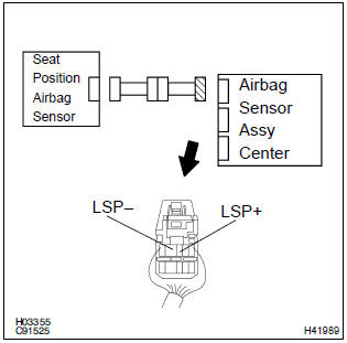
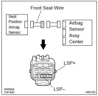
4 Check seat position airbag sensor circuit (open)(airbag sensor assy center – seat position airbag sensor)
Sst 09843–18040
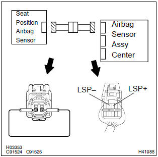
- Disconnect the connectors between the airbag sensor assy center and the seat position airbag sensor.
- using a service wire, connect lsp+ and lsp– of the connector (on the seat position airbag sensor side) between the airbag sensor assy center and the seat position airbag sensor.
- for the connector (on the airbag sensor assy center side)
between the airbag sensor assy center and the seat position
airbag sensor, measure the resistance between
lsp+ and lsp–.
Ok: resistance: below 1 Ω


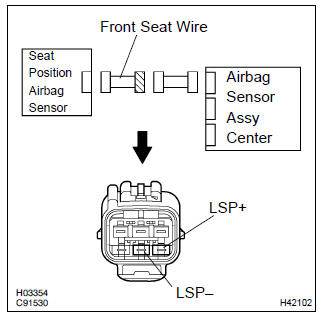
5 Check seat position airbag sensor circuit (to ground)(airbag sensor assy center – seat position airbag sensor)
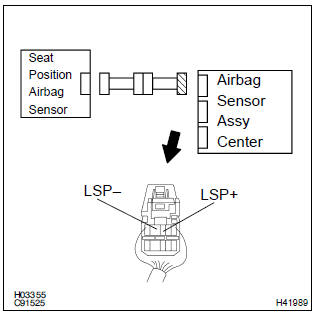
- Release the service wire of the connector (on the seat position airbag sensor side) between the seat position airbag sensor and the airbag sensor assy center.
- for the connector (on the airbag sensor assy center side)
between the airbag sensor assy center and the seat position
airbag sensor, measure the resistance between body
ground and each of lsp+ and lsp–.
Ok: resistance: 1 mΩ or higher


6 Check seat position airbag sensor circuit(airbag sensor assy center – seat position airbag sensor)
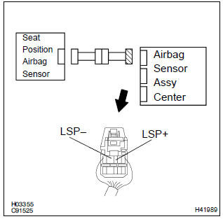
- For the connector (on the airbag sensor assy center side)
between the airbag sensor assy center and the seat position
airbag sensor, measure the resistance between
lsp+ and lsp–.
Ok: resistance: 1 mΩ or higher


7 Check seat position airbag sensor circuit (to b+)(airbag sensor assy center – seat position airbag sensor)
- Connect the negative (–) terminal cable to the battery, and wait at least for 2 seconds.
- turn the ignition switch to on.
- for the connector (on the airbag sensor assy center side)
between the airbag sensor assy center and the seat position
airbag sensor, measure the voltage between the
body ground and each of lsp+ and lsp–.
Ok: voltage: below 1 v


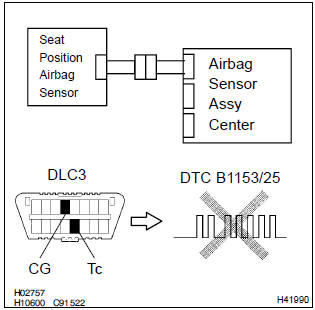
8 Check seat position air bag sensor
Sst 09843–18040
- Turn the ignition switch to lock.
- disconnect the negative (–) terminal cable from the battery, and wait at least for 90 seconds.
- connect the connectors of the seat position airbag sensor and the airbag sensor assy center.
- connect the negative (–) terminal cable to the battery, and wait at least for 2 seconds.
- turn the ignition switch to on, and wait at least for 20 seconds.
- clear the dtc stored in memory .
- turn the ignition switch to lock, and wait at least for 20 seconds.
- turn the ignition switch to on, and wait at least for 20 seconds.
- check the dtc .
Ok: dtc d1153/25 is not output.
Hint
: codes other that code b1153/25 may be output at this time, but they are not relevant to this check.


Use simulation method to check
9 Check air bag sensor assy center
Sst 09843–18040
- Turn the ignition switch to lock.
- disconnect the negative (–) terminal cable from the battery, and wait at least for 90 seconds.
- connect the connector of a new seat position airbag sensor.
- connect the negative (–) terminal cable to the battery, and wait at least for 2 seconds.
- turn the ignition switch to on, and wait at least for 20 seconds.
- clear the dtc stored in memory .
- turn the ignition switch to lock, and wait at least for 20 seconds.
- turn the ignition switch to on, and wait at least for 20 seconds.
- check the dtc .
Ok: dtc d1153/25 is not output.
Hint
: codes other that code b1153/25 may be output at this time, but they are not relevant to this check.


Use simulation method to check
10 Check wire harness(seat position airbag sensor – front seat inner belt assy)
Sst 09843–18040
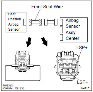
- Disconnect the front seat wire connector on the airbag sensor assy center side.
- for the front seat wire connector (on the airbag sensor
assy center side) between the airbag sensor assy center
and the seat position airbag sensor, measure the resistance
between lsp+ and lsp–.
Ok: resistance: below 1 Ω

Repair or replace instrument panel wire no.3(Airbag sensor assy center – front seat inner belt assy)
11 Check wire harness(seat position airbag sensor – front seat inner belt assy)
- Disconnect the front seat wire connector on the airbag sensor assy center side.
- for the front seat wire connector (on the airbag sensor
assy center side) between the airbag sensor assy center
and the seat position sensor, measure the resistance between
body ground and each of lsp+ and lsp–.
Ok: resistance: 1 mΩ or higher

Repair or replace instrument panel wire no.3(Airbag sensor assy center – front seat inner belt assy)
12 Check wire harness(seat position airbag sensor – front seat inner belt assy)
- Disconnect the negative (–) terminal cable from the battery, and wait at least for 90 seconds.
- disconnect the front seat wire connector on the airbag sensor assy center side.
- connect the negative (–) terminal cable to the battery, and wait at least for 2 seconds.
- turn the ignition switch to on, and wait at least for 60 seconds.
- for the front seat wire connector (on the airbag sensor
assy center side) between the front seat inner belt assy
and the seat position airbag sensor, measure the voltage
between body ground and each of lsp+ and lsp–.
Ok: voltage: below 1 v

Repair or replace instrument panel wire no.3(Airbag sensor assy center – front seat inner belt assy)
13 Check wire harness(seat position airbag sensor – front seat inner belt assy)
- Turn the ignition switch to lock.
- for the front seat wire connector (on the airbag sensor
assy center side) between the airbag sensor assy center
and the seat position sensor, measure the resistance between
lsp+ and lsp–.
Ok: resistance: 1 mΩ or higher

Repair or replace instrument panel wire no.3(Airbag sensor assy center – front seat inner belt assy)


Other materials:
Starting the engine
1 Continuously variable transmission: Ensure that the shift lever is in P and
depress the brake pedal.
Manual transmission: Shift the shift lever to N and depress the clutch pedal.
2 Touch the Toyota emblem side of the electronic key to the engine switch.
When the electronic key is detected, a ...
Inspection procedure
Hint:
read freeze frame data using the hand-held tester or the obd ii scan tool.
Freeze frame data records the
engine conditions when a malfunction is detected. When troubleshooting, it is
useful for determining whether
the vehicle was running or stopped, the engine was warmed up or not, the ...
Disposal
1. Dispose shock absorber assy rear lh
Fully extend the shock absorber rod.
using a drill, make a hole in the cylinder as shown in the
illustration to discharge the gas inside.
Caution:
when drilling, chips may fly out, work carefully.
The gas is colorless, odorless and no ...