Toyota Corolla (E120) 2002–2008 Repair Manual / Diagnostics / Supplemental restraint system / Side airbag sensor assy (lh)
malfunction / Inspection procedure
Toyota Corolla (E120): Inspection procedure
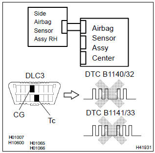
1 Check side air bag sensor assy lh
Sst 09843–18040
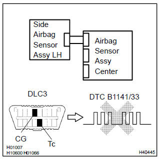
- Connect the negative (–) terminal cable to the battery, and wait at least for 2 seconds.
- turn the ignition switch to on, and wait at least for 20 seconds.
- clear the dtc stored in memory .
- turn the ignition switch to lock, and wait at least for 20 seconds.
- turn the ignition switch to on, and wait at least for 20 seconds.
- check the dtc .
Ok: dtc b1141/33 is not output.


2 Check airbag sensor assy center connector
- Turn the ignition switch to lock.
- disconnect the negative (–) terminal cable from the battery, and wait at least for 90 seconds.
- check that the connectors is properly connected to the airbag sensor assy center.


3 Check side airbag sensor assy connector
- Check that the connector is properly connected to the side airbag sensor assy (lh).


4 Check side airbag sensor assy(lh) circuit(open)(airbag sensor assy center – side airbag sensor assy lh)
Sst 09843–18040
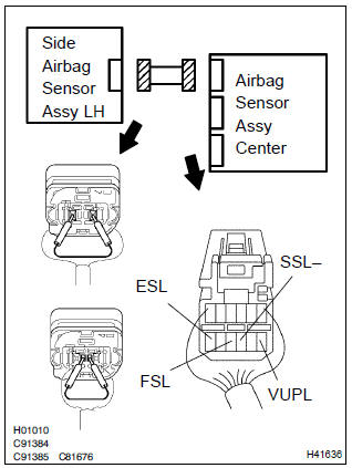
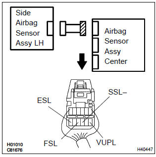
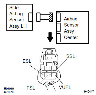
- Disconnect the connectors between the airbag sensor assy center and the side airbag sensor assy lh.
- using a service wire, connect vupl and esl, and fsl and ssl– of the connector (on the side airbag sensor assy side) between the airbag sensor assy center and the side airbag sensor assy (lh).
- for the connector (on the airbag sensor assy center side)
between the airbag sensor assy center and the side airbag
sensor assy (lh), measure the resistance between
vupl and esl, and between fsl and ssl–.
Ok: resistance: below 1 w

5 Check side airbag sensor assy(lh) circuit(to ground)(airbag sensor assy center – side airbag sensor assy lh)
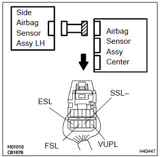
- Disconnect the connection between vupl and esl, and between fsl and ssl–.
- for the connector (on the airbag sensor assy center side)
between the airbag sensor assy center and the side airbag
sensor assy (lh), measure the resistance between
each terminal of vupl, ssl– and fsl, and body ground.
Ok: resistance: 1mΩ or higher

6 Check side airbag sensor assy(lh) circuit(airbag sensor assy center – side airbag sensor assy lh)
- For the connector (on the airbag sensor assy center side)
between the airbag sensor assy center and the side airbag
sensor assy (lh), measure the resistance between
vupl and esl, and between fsl and ssl–.
Ok: resistance: 1mΩ or higher

7 Check side airbag sensor assy(lh) circuit(to b+)(airbag sensor assy center – side airbag sensor assy lh)
- Connect the negative (–) terminal cable to the battery, and wait at least for 2 seconds.
- turn the ignition switch to on.
- for the connector (on the airbag sensor assy center side)
between the airbag sensor assy center and the side airbag
sensor assy (lh), measure the voltage between
each terminal of vupl, ssl– and fsl, and body ground.
Ok: voltage: below 1v

8 Check side air bag sensor assy lh
Sst 09843–18040
- Turn the ignition switch to lock.
- disconnect the negative (–) terminal cable from the battery, and wait at least for 90 seconds.
- connect the airbag sensor assy center connector.
- interchange the side airbag sensor assy (lh) and rh and connect the connectors to them.
- connect the negative (–) terminal cable to the battery, and wait at least for 2 seconds.
- turn the ignition switch to on, and wait at least for 20 seconds.
- clear the dtc stored in memory .
- turn the ignition switch to lock, and wait at least for 20 seconds.
- turn the ignition switch to on, and wait at least for 20 seconds.
- check the dtc .
Ok: (a): dtc b1140/32 is not output.
(B): dtc b1141/33 is not output.

9 Use simulation method to check


Replace all srs components including the wire harness


Other materials:
Foreword
This repair manual has been prepared to provide essential information
on body panel repair methods (including cutting and
welding operations, but excluding painting) for the toyota
corolla
Applicable models: aze141 series
zre142 series
This manual consists of body repair methods, exploded diag ...
How to proceed with troubleshooting
The hand–held tester can be used at step 4, 6, 8 and 9.
1 Vehicle brought to workshop
2 Customer problem analysis
3 Warning light check
4 The dtcs check (present and past dtcs)
5 The dtcs chart
6 Circuit inspection
7 Repair
8 Clear the dtcs (present and past dtcs)
9 The dt ...
Brake fluid
■ Checking fluid level
The brake fluid level should be between the “MAX” and “MIN” lines on the tank.
■ Adding fluid
Make sure to check the fluid type and prepare the necessary item.
1 Slide and lift up the rubber strip to partially remove it as shown.
2 Disconnect the ...