Toyota Corolla (E120): Inspection procedure
1 Inspect transmission wire(slt)
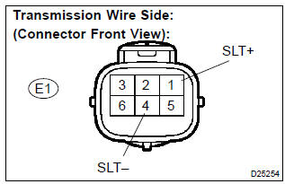
- Disconnect the transmission wire connector from the transaxle.
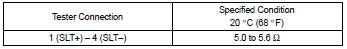
- measure the resistance according to the value(s) in the table below.
Standard:
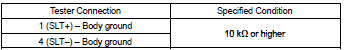
- Measure the resistance according to the value(s) in the
table below.
Standard (check for short):


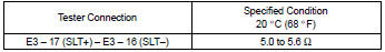
2 Check harness and connector(transmission wire – ecm)
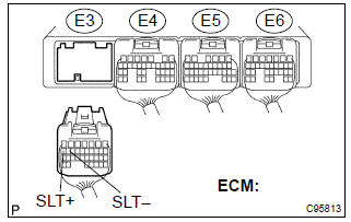
- Connect the transmission wire connector to the transaxle.
- disconnect the ecm connector.
- measure the resistance according to the value(s) in the table below.
Standard:
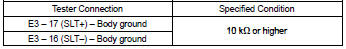
- Measure the resistance according to the value(s) in the table below.
Standard (check for short):

Replace ecm
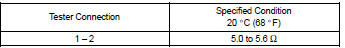
3 Inspect shift solenoid valve(slt)
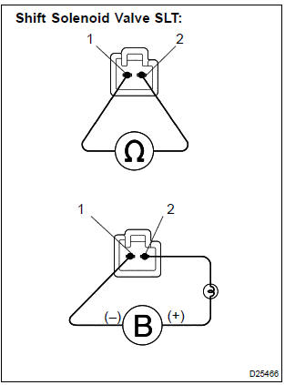
- Remove the shift solenoid valve (slt).
- measure the resistance according to the value(s) in the table below.
Standard:
- Connect the positive (+) battery lead with a 21 w bulb to the terminal 2 of the solenoid valve connector and the negative (–) battery lead to the terminal 1 of the solenoid valve connector for checking the solenoid valve operation.
Standard: the solenoid makes an operating noise.


Repair or replace transmission wire


Other materials:
Light control switch circuit
Wiring diagram
Inspection procedure
1 Check headlamp dimmer switch assy (light control switch)
2 Check wire harness (tvip ecu light control switch)
Disconnect the tvip ecu and light control switch connectors.
check the continuity between the terminals of the tvip
e ...
For your information
Main Owner’s Manual
Please note that this manual applies to all models and explains all equipment,
including options. Therefore, you may find some explanations for equipment not installed
on your vehicle.
All specifications provided in this manual are current at the time of printing.
Howeve ...
Inspection
1. Cooler thermistor no.1
Check resistance between terminals 1 and 2 of cooler
thermistor no. 1 At each temperature, as shown in the
chart.
Resistance:
If resistance value is not as specified, replace the sensor.
2. Cooler and accessory assy
Inspect blower switch contin ...