Toyota Corolla (E120) 2002–2008 Repair Manual / Diagnostics / ABS with EBD system / Malfunction in abs ecu / Inspection procedure
Toyota Corolla (E120): Inspection procedure
1 Reconfirm dtc
- Check the dtc

2 Inspect skid control ecu connector securely connected


3 Inspect skid control ecu connector(ig1 terminal voltage)
In case of using hand–held tester:
- check the voltage condition output from the ecu displayed on the
hand–held tester.
Ok: ”normal” is displayed.
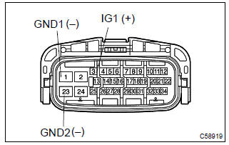
In case of not using hand–held tester:
- disconnect the skid control ecu connector.
- turn the ignition switch to on.
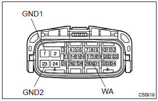
- measure voltage between terminals ig1 (3) and gnd (1,
23) of skid control ecu harness side connector.
Ok: oltage: 10 – 14 v


4 Inspect skid control ecu connector(gnd terminal continuity)
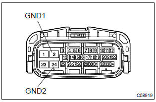
- Measure resistance between terminal gnd (s1–2, 24) of
skid control ecu harness side connector and body
ground.
Resistance: 1 Ω or less

Check and repair harness and connector
5 Go to combination meter system(abs warning light)
- Disconnect the skid control ecu connector.
- using service wire, connect terminals wa (30) and gnd (1, 23) of skid control ecu harness side connector.
- turn the ignition switch to on.
Ok: abs warning light goes off.

Check and replace brake actuator assy


Other materials:
Brake
Service data
Torque specification
Parking brake
Service data
Torque specification
...
Using automatic mode
1 Press .
The dehumidification function begins to operate. Air outlets and fan speed are
automatically adjusted according to the temperature setting.
2 Adjust the temperature setting.
3 To stop the operation, press again.
■ If the system is operated manually in automatic mode
If the fa ...
Installing child restraints using a seat belt
■ Rear-facing - Infant seat/convertible seat
1 Place the child restraint system on the rear seat facing the rear of the vehicle.
2 Run the seat belt through the child restraint system and insert the plate into
the buckle. Make sure that the belt is not twisted.
3 Fully extend the shou ...