Toyota Corolla (E120) 2002–2008 Repair Manual / Diagnostics / Sfi system / Catalyst system efficiency below
threshold / Inspection procedure
Toyota Corolla (E120): Inspection procedure
Hint
: read freeze frame data using the hand-held tester or the obd ii scan tool. Freeze frame data records the engine conditions when a malfunction is detected. When troubleshooting, it is useful for determining whether the vehicle was running or stopped, the engine was warmed up or not, the air–fuel ratio was lean or rich, etc. At the time of the malfunction.
1 Check other dtc output(in addition to dtc p0420)
- Connect the hand–held tester or the obd ii scan tool to the dlc3.
- turn the ignition switch on and push the hand–held tester or the obd ii scan tool main switch on.
- select the item ”diagnosis / enhanced obd ii / dtc info / current codes”.
- read the dtcs.
Result:

Hint
: if any other codes besides p0420 are output, perform the troubleshooting for those dtcs first.

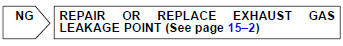
2 Check for exhaust gas leakage

3 Inspect heated oxygen sensor(bank 1 sensor 1)
Refer to the hint below.

4 Inspect heated oxygen sensor(bank 1 sensor 2)
Refer to the hint below.

Replace three–way catalytic converter(exhaust manifold)
Hint
: hand–held tester only:
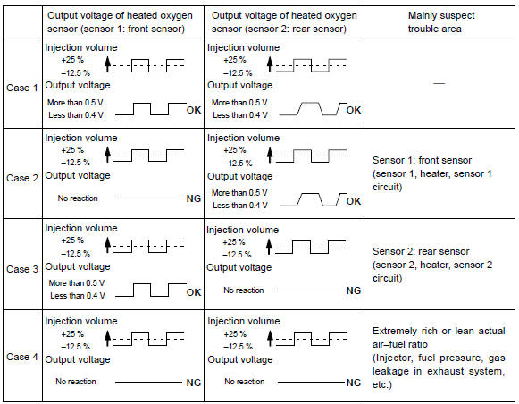
- the following procedure enables the technician to identify a trouble area if malfunction in both front and rear heated oxygen sensors other than the catalyst converter, or the malfunction that indicates the actual air–fuel ratio extremely rich or lean.
- Narrowing down the trouble area is possible by performing ”a/f control” active test (heated oxygen sensor or other trouble areas can be distinguished).
- Perform active test using hand–held tester (a/f control).
Hint
: ”a/f control” is active test which changes the injection volume –12.5 % Or +25 %.
- Connect the hand–held tester to the dlc3 on the vehicle.
- Turn the ignition switch on.
- Warm up the engine by running the engine speed at 2,500 rpm for approximately 90 seconds.
- Select the item ”diagnosis / enhanced obd ii / active test / a/f control”.
- Perform ”a/f control” with the engine in an idle condition (press the right or left button).
Result:
heated oxygen sensor reacts in accordance with increase and decrease of
injection volume
+25 % rich output: more than 0.5 V,
–12.5 % Lean output: less than 0.4 V
Notice
: there is a delay of few seconds in the sensor 1 (front sensor) output, and there is about 20 seconds delay at maximum in the sensor 2 (rear sensor).
The following of a/f control procedure enables the technician to check and graph the voltage outputs of both the heated oxygen sensors.
For displaying the graph indication, enter ”active test / a/f control / user data”, then select ”o2s b1s1 and o2s b1s2” by pressing ”yes” button and push ”enter” button before pressing ”f4” button.


Other materials:
Circuit description
The throttle pressure that is applied to the primary regulator
valve (which modulates the line pressure) causes the solenoid
valve slt, under electronic control, to precisely and minutely
modulate and generate the line pressure according the extent
of the accelerator pedal depressed or the o ...
Replacement
Hint: components:
1. Remove rear wheel
2. Remove rear brake drum sub–assy
3. Disconnect skid control sensor wire (w/ abs)
4. Remove rear axle hub & bearing assy lh
Remove the 4 bolts and hub & bearing assy lh.
5. Install rear axle hub & bearing assy lh
Install t ...
Dialing from call histories
1 Select “All calls”, “Missed calls”, “Incoming calls” or “Outgoing calls” using
.
2 Select the desired number using
and press the off-hook switch.
The following operations can be performed:
● Registering a number as a speed dial
Press (Add S. Dial) and then press
an ...