Toyota Corolla (E120) 2002–2008 Repair Manual / Diagnostics / Sfi system / Camshaft position sensor ”a”
circuit / Inspection procedure
Toyota Corolla (E120): Inspection procedure
Hint
: read freeze frame data using the hand-held tester or the obd ii scan tool. Freeze frame data records the engine conditions when a malfunction is detected. When troubleshooting, it is useful for determining whether the vehicle was running or stopped, the engine was warmed up or not, the air–fuel ratio was lean or rich, etc. At the time of the malfunction.
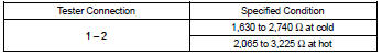
1 Inspect camshaft position sensor(resistance)
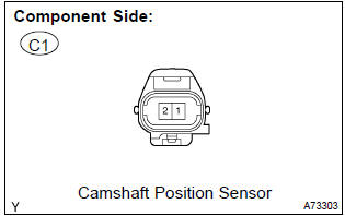
- Measure the resistance between the terminals of camshaft position sensor connector.
Standard:
Notice
: ”cold” and ”hot” shown above mean the temperature of the coils themselves. ”Cold” is from –10 c (14 f) to 50 c (122 f) and ”hot” is from 50 c (122 f) to 100 c (212 f).


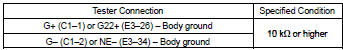
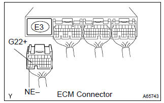
2 Check harness and connector(camshaft position sensor – ecm)
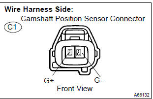
- Disconnect the c1 camshaft position sensor connector.
- disconnect the e3 ecm connector.
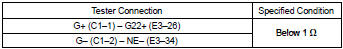
- check the resistance between the wire harness side connectors.
Standard (check for open):
Standard (check for short):
- Reconnect the ecm connector.
- reconnect the camshaft position sensor connector.

3 Check sensor installation(camshaft position sensor)
- Check the camshaft position sensor installation.


4 Check camshaft timing gear assy(teeth of plate)
- Check the teeth of the signal plate.


Replace ecm


Other materials:
Sound setting
1 Display the “Phone/Message Settings” screen. 2 Select “Sound Settings” on the
“Phone/Message Settings” screen.
1 Set the desired ringtone.
2 Adjust the ringtone volume.
3 Adjust the message readout volume.
4 Set the desired incoming SMS/MMS tone.
5 Adjust the incoming SMS/ MMS t ...
Precaution
Caution:
replace the faulty parts of the seat belt systems (outer belt, inner belt,
bolts, nuts, adjustable shoulder
anchor, tether anchor hardware, sill–bar, etc.).
Seat belt systems not in use at the time of a collision should also be inspected
and replaced if found
to be damaged or wo ...
Correct use of the seat
belts
Extend the shoulder belt so
that it comes fully over the
shoulder, but does not come
into contact with the neck or
slide off the shoulder.
Position the lap belt as low as
possible over the hips.
Adjust the position of the
seatback. Sit up straight and
well back in the seat.
Do not twist ...