Toyota Corolla (E120) 2002–2008 Repair Manual / Diagnostics / Sfi system / Oxygen sensor circuit malfunction / Inspection procedure
Toyota Corolla (E120): Inspection procedure
Hint
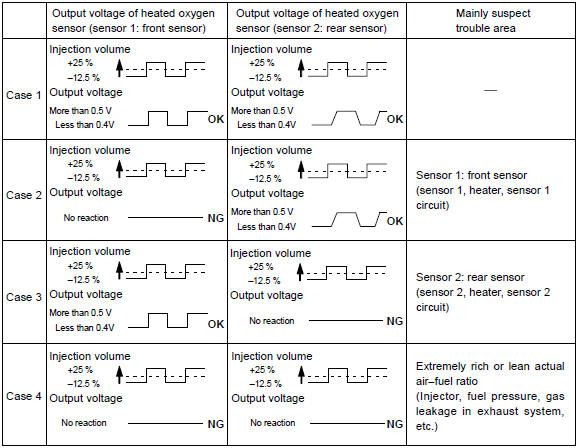
: hand–held tester only: narrowing down the trouble area is possible by performing ”a/f control” active test (heated oxygen sensor or other trouble areas can be distinguished).
- Perform active test using hand–held tester (a/f control).
Hint
: ”a/f control” is the active test which changes the injection volume to –12.5 % Or +25 %.
- Connect the hand–held tester to the dlc3 on the vehicle.
- Turn the ignition switch on.
- Warm up the engine by running the engine speed at 2,500 rpm for approximately 90 seconds.
- Select the item ”diagnosis / enhanced obd ii / active test / a/f control”.
- Perform ”a/f control” with the engine in an idle condition (press the right or left button).
Result:
heated oxygen sensor reacts in accordance with increase and decrease of
injection volume
+25 % " rich output: more than 0.5 V,
–12.5 % " Lean output: less than 0.4 V
Notice
: there is a delay of few seconds in the sensor 1 (front sensor) output, and there is about 20 seconds delay at maximum in the sensor 2 (rear sensor).
The following of a/f control procedure enables the technician to check and graph the voltage outputs of both the heated oxygen sensors.
For displaying the graph indication, enter ”active test / a/f control / user data”, then select ”o2s b1s1 and o2s b1s2” by pressing ”yes” button and push ”enter” button before pressing ”f4” button.
Hint
:
- if different dtcs related to different systems that have terminal e2 as the ground terminal are output simultaneously, terminal e2 may be open.
- Read freeze frame data using the hand-held tester or the obd ii scan tool. Freeze frame data records the engine conditions when a malfunction is detected. When troubleshooting, it is useful for determining whether the vehicle was running or stopped, the engine was warmed up or not, the air–fuel ratio was lean or rich, etc. At the time of the malfunction.
1 Check other dtc output(in addition to dtc p0136)
- Connect the hand–held tester or the obd ii scan tool to the dlc3.
- turn the ignition switch on and push the hand–held tester or the obd ii scan tool main switch on.
- select the item ”diagnosis / enhanced obd ii / dtc info / current codes”.
- read the dtcs.
Result:

Hint
: if any other codes besides p0136 are output, perform the troubleshooting for those dtcs first.


2 Read value of hand–held tester or obd ii scan tool(output voltage of heated oxygen sensor)
- Connect the hand–held tester or the obd ii scan tool to the dlc3.
- start the engine and push the hand–held tester or the obd ii scan tool main switch on.
- select the item ”diagnosis / enhanced obd ii / data list / all / o2s b1s2”.
- after warming up the engine, run the engine at 2,500 rpm for 3 minutes.
- read the output voltage of the heated oxygen sensor (sensor 2) when the engine rpm is suddenly increased
Hint
: quickly accelerate the engine to 4,000 rpm 3 times by using the accelerator pedal.
Standard: the output voltage of heated oxygen sensor (sensor 2): alternates from 0.4 V or less to 0.5 V or more.


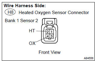
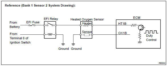
3 Inspect heated oxygen sensor(heater resistance)
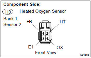
- Disconnect the h8 heated oxygen sensor connector.
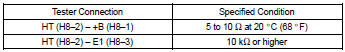
- measure the resistance between the terminals of the heated oxygen sensor connector.
Standard:
- Reconnect the heated oxygen sensor connector.


4 Inspect efi relay
- Remove the efi relay from the engine room r/b.
- check for continuity in the efi relay.
Standard:
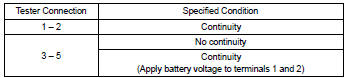
- Reinstall the efi relay.


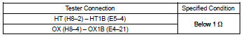
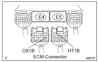
5 Check harness and connector(heated oxygen sensor – ecm)
- Disconnect the h8 heated oxygen sensor connector.
- disconnect the e4 and e5 ecm connector.
- check the resistance between the wire harness side connectors.
Standard (check for open):
Standard (check for short):
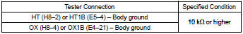
- Reconnect the ecm connector.
- reconnect the heated oxygen sensor connector.

Replace heated oxygen sensor
6 Perform confirmation driving pattern
Hint
: clear all dtcs prior to performing the confirmation driving pattern.

7 Read output dtc(dtc p0136 is output again)
- Connect the hand–held tester or the obd ii scan tool to the dlc3.
- turn the ignition switch on and push the hand–held tester or the obd ii scan tool main switch on.
- select the item ”diagnosis / enhanced obd ii / dtc info / current codes”.
- read the dtcs.
Result:


Replace heated oxygen sensor


Other materials:
Using the rear view monitor system
■ Screen description
1 Vehicle width guide lines
The line indicates a guide path when the vehicle is being backed straight up.
The displayed width is wider than the actual vehicle width.
2 Vehicle center guide lines
These lines indicate the estimated vehicle center on the ground.
3 Dis ...
Inspection procedure
1 Inspect dlc3 terminal voltage
Turn the ignition switch to on.
measure voltage between terminals 13 (tc) and 4 (cg) of
dlc3.
Ok:
voltage: 10 – 16 v
2 Check harness and connector(between cruise control ecu assy
and dlc3)
Check for open and short circuit in harness ...
Circuit description
The seat belt buckle switch (lh) circuit consists of the airbag sensor assy
center and front seat inner belt
assy (lh).
Dtc b0126/b0127/27 is recorded when a malfunction is detected in the seat belt
buckle switch (lh) circuit.
Wiring diagram
...