Toyota Corolla (E120) 2002–2008 Repair Manual / Diagnostics / Sfi system / Engine coolant temperature circuit / Inspection procedure
Toyota Corolla (E120): Inspection procedure
Hint
:
- if different dtcs related to different systems that have terminal e2 as the ground terminal are output simultaneously, terminal e2 may be open.
- Read freeze frame data using the hand-held tester or the obd ii scan tool. Freeze frame data records the engine conditions when a malfunction is detected. When troubleshooting, it is useful for determining whether the vehicle was running or stopped, the engine was warmed up or not, the air–fuel ratio was lean or rich, etc. At the time of the malfunction.
1 Read value of hand–held tester or obd ii scan tool(engine coolant temperature)
- Connect the hand–held tester or the obd ii scan tool to the dlc3.
- turn the ignition switch on and push the hand–held tester or the obd ii scan tool main switch on.
- select the item ”diagnosis / enhanced obd ii / data list / all / coolant temp” and read its value displayed on the hand–held tester or the obd ii scan tool.
Temperature: same value as the actual intake air temperature.
Result:
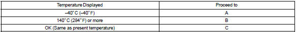
Hint
: if there is an open circuit, the hand–held tester or the obd ii scan tool indicates –40 °C (–40°f).
If there is a short circuit, the hand–held tester or the obd ii scan tool indicates 140 °C (284°f) or more.

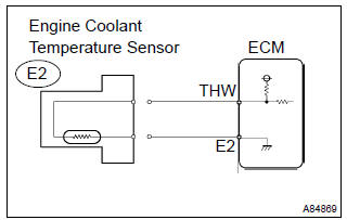
2 Read value of hand–held tester or obd ii scan tool(check for open in wire harness)
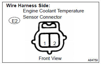
- Disconnect the e2 engine coolant temperature sensor connector.
- connect terminals 1 and 2 of the engine coolant temperature sensor connector on the wire harness side.
- turn the ignition switch on.
- select the item ”diagnosis / enhanced obd ii /
data list / all / coolant temp” and read its value
displayed on the hand–held tester or the obd ii scan tool.
Temperature value: 140 °C (284°f) or more
- reconnect the engine coolant temperature sensor connector.

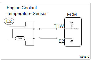
3 Read value of hand–held tester or obd ii scan tool(check for open in ecm)
- Disconnect the e2 engine coolant temperature sensor connector.
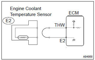
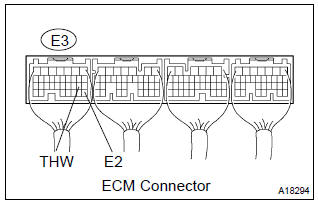
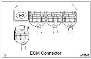
- connect the terminals thw and e2 of the e3 ecm connector.
Hint
: before checking, do a visual and contact pressure check on the ecm connector.
- turn the ignition switch on.
- select the item ”diagnosis / enhanced obd ii /
data list / all / coolant temp” and read its value
displayed on the hand–held tester or the obd ii scan tool.
Temperature value: 140 °C (284°f) or more
- reconnect the engine coolant temperature sensor connector.

Confirm good connection at ecm. If ok, replace ecm
4 Read value of hand–held tester or obd ii scan tool(check for short in wire harness)
- Disconnect the e2 engine coolant temperature sensor connector.
- turn the ignition switch on.
- select the item ”diagnosis / enhanced obd ii /
data list / all / coolant temp” and read its value
displayed on the hand–held tester or the obd ii scan tool.
Temperature value: –40 °C (–40°f)
- reconnect the engine coolant temperature sensor connector.

5 Read value of hand–held tester or obd ii scan tool(check for short in ecm)
- Disconnect the e3 ecm connector.
- turn the ignition switch on.
- ) select the item ”diagnosis / enhanced obd ii /
data list / all / coolant temp” and read its value
displayed on the hand–held tester or the obd ii scan tool.
Temperature: –40 °C (–40°f)
- reconnect the ecm connector.

Replace ecm


Other materials:
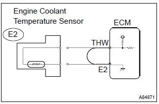
Circuit description
In the diagram below, when the engine is cranked, current flows from terminal
st2 of the ignition switch to
the starter relay coil and also current flows to terminal sta of the ecm (sta
signal).
When the sta signal and ne signal are input to the ecm, tr is turned on, current
flows to the c ...
Cassette tape cannot be ejected
Wiring diagram
Wiring diagram
1 Check if radio auto–search functions properly
Check if the radio auto–search function properly.
Perform the auto–research of the radio and check that the
operation is normal.
Standard: malfunction disappear.
2 Press ”eject” and ...
Seat belt warning lamp for front passenger’s seat
does not flash
Wiring diagram
Inspection procedure
1 Inspect combination meter assy
Ground terminal c9–11 on the combination meter side.
check that the warning lightlights up.
Ok: warning light lights up.
2 Inspect passenger seat belt warning lamp assy
Ground terminal c9– ...